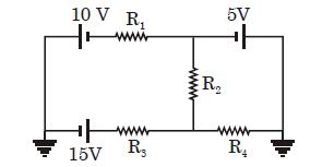
In the circuit shown, $R_1$ is increased. What happens to the reading of the voltmeter (ideal)?
Easy


Download our appand get started for free
Experience the future of education. Simply download our apps or reach out to us for more information. Let's shape the future of learning together!No signup needed.*
Similar Questions
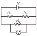
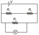
- 1Two resistances of $400$ $\Omega$ and $800$ $\Omega$ are connected in series with $6\, volt$ battery of negligible internal resistance. A voltmeter of resistance $10,000$ $\Omega$ is used to measure the potential difference across $400$ $\Omega$. The error in the measurement of potential difference in volts approximately isView Solution
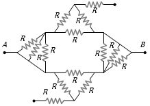
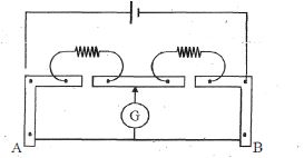
- 2Find equivalent resistance between $A$ and $B$View Solution
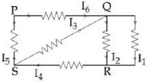
- 3In the given circuit diagram, the currents, ${I_1} = - \,0.3\,A,\,{I_4} = 0.8\,A$ and ${I_5} = 0.4\,A,$ are flowing as shown. The currents $I_2,\,I_3$ and $I_6,$ respectively areView Solution
- 4A meter bridge set up as shown to determine end correction at $A$ and $B$ . When a resistance of $15\,\Omega $ is used in left gap and of $20\,\Omega $ in right gap, then null point comes at a distance $42\ cm$ from $A$ . When these resistances are interchanged null point comes at a distance $57\ cm$ from $A$ . Values of end corrections areView Solution
- 5View SolutionOhm's law fails in
- 6$n$ identical cells each of $e.m.f.$ $E$ and internal resistance $r$ are connected in series. An external resistance $R$ is connected in series to this combination. The current through $R$ isView Solution
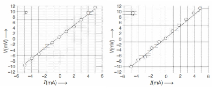
- 7Two students $P$ and $Q$ perform an experiment to verify Ohm's law for a conductor with resistance $R$. They use a current source and a voltmeter with least counts of $0.1 mA$ and $0.1 \,mV$, respectively. The plots of the variation of voltage drop $V$ across $R$ with current $I$ for both are shown below. The statement which is most likely to be correct?View Solution
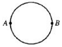
- 8A wire of resistance $12\,ohms$ per meter is bent to form a complete circle of radius $10\, cm.$ The resistance between its two diametrically opposite points, $A$ and $B$ as shown in the figure isView Solution
- 9$A$ constant voltage is applied between the two ends of a uniform metallic wire. Some heat is developed in it. The heat developed is doubled ifView Solution
- 10In the circuit shown, current through $R_2$ is zero. If $R_4 = 2\,\Omega $ and $R_3 = 4\,\Omega $ , current through $R_3$ will be ................. $\mathrm{A}$View Solution