If two bulbs of wattage $25$ and $30$, each rated at $220\, volts$, are connected in series with a $440$ $volt$ supply, which bulb will fuse
Easy


Download our appand get started for free
Experience the future of education. Simply download our apps or reach out to us for more information. Let's shape the future of learning together!No signup needed.*
Similar Questions
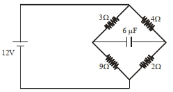
- 1In the circuit shown, the energy stored in the capacitor is $n\,\mu J$. The value of $n$ is ..............View Solution
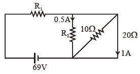
- 2In the circuit shown in the given figure the resistance $R_1$ and $R_2$ are respectivelyView Solution
- 3View SolutionWhich of the following statements is false?
- 4The current density in a cylindrical wire of radius $4 \; mm$ is $4 \times 10^{6} \; Am ^{-2}$. The current through the outer portion of the wire between radial distance $\frac{R}{2}$ and $R$ is $\dots \; \pi A .$View Solution
- 5A heater of $220\, V$ heats a volume of water in $5\,\min$ time. A heater of $110\, V$ heats the same volume of water in ............... $min$View Solution
- 6The resistivity of alloys $ = {R_{{\rm{alloy}}}}$; the resistivity of constituent metals ${R_{{\rm{metal}}}}$. Then, usuallyView Solution
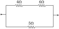
- 7In the circuit shown in figure, the heat produced in $5\, ohm $ resistance is $10\, cal / sec$ . The heat produced in $4$ resistance is ................ $cal /sec$View Solution
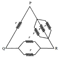
- 8Six equal resistances are connected between points $P, Q$ and $R$ as shown in figure. Then net resistance will be maximum betweenView Solution
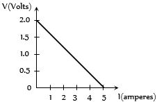
- 9For a cell, the graph between the potential difference $(V) $ across the terminals of the cell and the current $(I)$ drawn from the cell is shown in the figure. The $e.m.f.$ and the internal resistance of the cell areView Solution
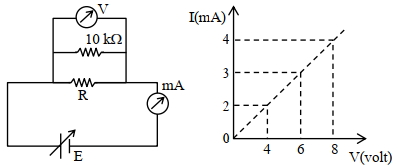
- 10To determine the resistance ($R$) of a wire, a circuit is designed below, The $V-I$ characteristic curve for this circuit is plotted for the voltmeter and the ammeter readings as shown in figure. The value of $\mathrm{R}$ is . . . . . . .$\Omega$View Solution