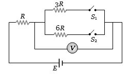
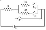
In Circuit-$1$ and Circuit- $2$ shown in the figures, $R_1=1 \Omega, R_2=2 \Omega$ and $R_3=3 \Omega$. $P_1$ and $P_2$ are the power dissipations in Circuit-$1$ and Circuit-$2$ when the switches $S_1$ and $S_2$ are in open conditions, respectively. $Q_1$ and $Q_2$ are the power dissipations in Circuit-$1$ and Circuit-$2$ when the switches $S_1$ and $S_2$ are in closed conditions, respectively.
Which of the following statement($s$) is(are) correct?
$(A)$ When a voltage source of $6 V$ is connected across $A$ and $B$ in both circuits, $P_1$
$(B)$ When a constant current source of $2 Amp$ is connected across $A$ and $B$ in both circuits, $P_1>P_2$.
$(C)$ When a voltage source of $6 V$ is connected across $A$ and $B$ in Circuit-$1$, $Q_1>P_1$.
$(D)$ When a constant current source of $2 Amp$ is connected across $A$ and $B$ in both circuits, $Q_2$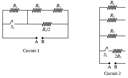
IIT 2022, Advanced


Download our appand get started for free
Experience the future of education. Simply download our apps or reach out to us for more information. Let's shape the future of learning together!No signup needed.*
Similar Questions
- 1In the following $'I'$ refers to current and other symbols have their usual meaning, Choose the option that corresponds to the dimensions of electrical conductivityView Solution
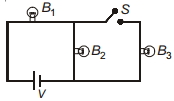
- 2Three identical bulbs $B_1, B_2$ and $B_3$ are connected to the mains as shown in figure. If $B_3$ is disconnected from the circuit by opening switch $S$, then incandescence of bulb $B_1$ willView Solution
- 3The resistance of a wire is $R$. It is bent at the middle by $180^{\circ}$ and both the ends are twisted together to make a shorter wire. The resistance of the new wire isView Solution
- 4A null point is found at $200\,cm$ in potentiometer when cell in secondary circuit is shunted by $5\,\Omega$. When a resistance of $15\,\Omega$ is used for shunting null point moves to $300\,cm$. The internal resistance of the cell is $..............\,\Omega$.View Solution
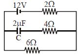
- 5Find the charge on the capacitor $C$ in the following circuit ............. $\mu C$View Solution
- 6In the circuit shown in figure reading of voltmeter is $V_1$ when only $S_1$ is closed, reading of voltmeter is $ V_2$ when only $S_2$ is closed and reading of voltmeter is $V_3$ when both $S_1$ and $S_2$ are closed. ThenView Solution
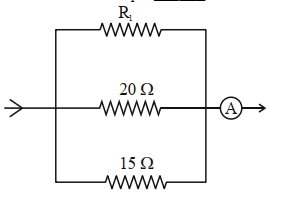
- 7In the given circuit, the current flowing through the resistance $20\ \Omega$ is $0.3 \mathrm{~A}$, while the ammeter reads $0.9 \mathrm{~A}$. The value of $\mathrm{R}_1$ is_____________ $\Omega$.View Solution
- 8In the circuit shown in figure reading of voltmeter is $V_1$ when only $S_1$ is closed, reading of voltmeter is $V_2$ when only $S_2$ is closed. The reading of voltmeter is $V_3$ when both $S_1$ and $S_2$ are closed thenView Solution
- 9This question contains statement$-1$ and statement$-2$. Of the four choices given after the statements, choose the one that best describes the two statements.View Solution
statement$-1$ : The temperature dependence of resistance is usually given as $R=R_{0}(1+\alpha \Delta t)$. The resistance of a wire changes from $100\; \Omega$ to $150\; \Omega$ when its temperature is increased from $27^{\circ} C$ to $227^{\circ} C$. This implies that $\alpha=2.5$ $\times 10^{-3} /{ }^{\circ} C$
statement$-2\;: R=R_{0}(1+\alpha \Delta t)$ is valid only when the change in the temperature $\Delta T$ is small and $\Delta R=\left(R-R_{0}\right) < < R_{0}$
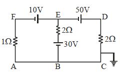
- 10The potential at point $E$ for the given figure is ................ $\mathrm{V}$View Solution