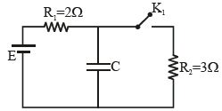
In the circuit shown in the figure $K_1$ is open. The charge on capacitor $C$ in steady state is $q_1$. Now key is closed and at steady state charge on $C$ is $q_2$. The ratio of charges $q_1/q_2$ is
Diffcult
Download our app for free and get started
When key is open
$\mathrm{V}_{\mathrm{C}}=\mathrm{E} \Rightarrow \mathrm{q}_{1}=\mathrm{CE}$
When key is closed
$\mathrm{V}_{\mathrm{C}}^{1}=\frac{\mathrm{E}}{2+3} \times 3=\frac{3}{5} \mathrm{E}$
$\therefore $ $\mathrm{q}_{2}=\mathrm{CV}_{\mathrm{C}}^{1}=\mathrm{C} \times \frac{3}{5} \mathrm{E}=\frac{3}{5} \mathrm{q}_{1} \Rightarrow \frac{\mathrm{q}_{1}}{\mathrm{q}_{2}}=\frac{5}{3}$

Download our appand get started for free
Experience the future of education. Simply download our apps or reach out to us for more information. Let's shape the future of learning together!No signup needed.*
Similar Questions
- 1View SolutionElectric current has both magnitude and direction. It is a
- 2In a potentiometer, the null point is received at $7^{th}$ wire. If now we have to change the null point at $9^{th}$ wire, what should we do ?View Solution
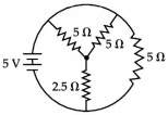
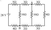
- 3The total current supplied to the circuit as shown in figure by the $5 V$ battery is $A$View Solution
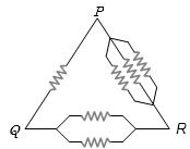
- 4Six equal resistances are connected between points $P$, $Q$ and $R$ as shown in the figure. Then the net resistance will be maximum betweenView Solution
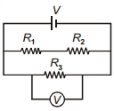
- 5In the circuit shown, $R_1$ is increased. What happens to the reading of the voltmeter (ideal)?View Solution
- 6View SolutionConsider the circuit shown in the figure
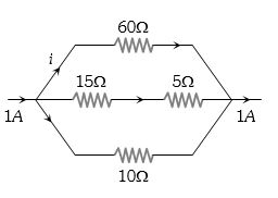
- 7The magnitude of $i$ in ampere unit isView Solution
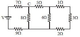
- 8In the ladder network shown, current through the resistor $3\, \Omega$ is $0.25\,A$. The input voltage $'V'$ is equal to:- ........... $V$View Solution
- 9View SolutionWhich of the following quantities do not change when a resistor connected to a battery is heated due to the current?
- 10The series combination of two batteries, both of the same emf $10 \mathrm{\;V},$ but different internal resistance of $20\; \Omega$ and $5\; \Omega,$ is connected to the parallel combination of two resistors $30\; \Omega$ and $\mathrm{R}\; \Omega .$ The voltage difference across the battery of internal resistance $20\; \Omega$ is zero, the value of $\mathrm{R}(\text { in } \Omega)$ isView Solution