In the electrical circuit shown in the figure, the current $i$ through the side $AB$ is
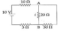
NEET 2017, Medium
Download our app for free and get started
$R_{eq}=25 \Omega$
$I=\frac{10}{25}$
$I=0.4$
$I_{(20\;\Omega)}=\frac{30 \times \frac{4}{10}}{20+30}=\frac{12}{50}=\frac{6}{25} A$

Download our appand get started for free
Experience the future of education. Simply download our apps or reach out to us for more information. Let's shape the future of learning together!No signup needed.*
Similar Questions
- 1The resistance of a coil is $4.2\, \Omega$ at $100\,^o C$ and the temperature coefficient of resistance of its material is $ 0.004\,^o C$. Its resistance at $0\,^o C$ is ............. $\Omega$View Solution
- 2The resistor of resistance '$R$' is connected to $25\, V$ supply and heat produced in it is $25\, J/sec$. The value of $R$ is .......... $\Omega $View Solution
- 3A $2\, W$ carbon resistor is color coded with green, black, red and brown respectively. The maximum current which can be passed through this resistor is .............. $mA$View Solution
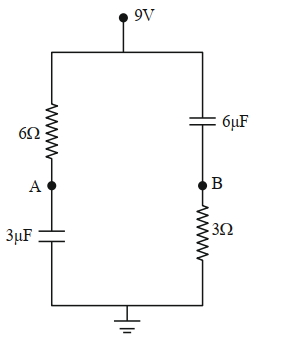
- 4In the given figure, the charge stored in $6 \ \mu \mathrm{F}$ capacitor, when points $A$ and $B$ are joined by a connecting wire is___________ $\mu \mathrm{C}$.View Solution
- 5Four resistances $10$ $\Omega$, $5$ $\Omega$, $7$ $\Omega$ and $3$ $\Omega$ are connected so that they form the sides of a rectangle $AB$, $BC$, $CD$ and $DA$ respectively. Another resistance of $10$ $\Omega$ is connected across the diagonal $AC$. The equivalent resistance between $A$ and $B $ is .............. $\Omega$View Solution
- 6The value of the resistance $R$ in figure is adjusted such that power dissipated in the $2\,\Omega $ resistor is maximum. Then the power dissipated in the $2\,\Omega $ will be ................ $W$View Solution
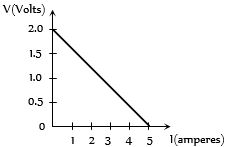
- 7For a cell, the graph between the potential difference $(V) $ across the terminals of the cell and the current $(I)$ drawn from the cell is shown in the figure. The $e.m.f.$ and the internal resistance of the cell areView Solution
- 8Find the error in reading of voltmeter ................ $\%$View Solution
- 9In the circuit shown, the reading of the Ammeter is doubled after the switch is closed. Each resistor has a resistance $ = 1\,\Omega $ and the ideal cell has an $e.m.f. = 10\, V$. Then, the Ammeter has a coil resistance equal to ................ $\Omega$View Solution
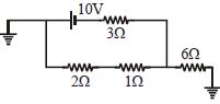
- 10Find current in $6\,\Omega $ resistanceView Solution