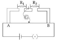
In the experimental setup of meter bridge shown in the figure, the null point is obtained at a distance of $40\,cm$ from $A$. If a $10\,\Omega $ resistor is connected in series with $R_1$, the null point shifts by $10\,cm$. The resistance that should be connected in parallel with $\left( {{R_1} + 10} \right)\,\Omega $ such that the null point shifts back to its initial position is .............. $\Omega$
JEE MAIN 2019, Diffcult


Download our appand get started for free
Experience the future of education. Simply download our apps or reach out to us for more information. Let's shape the future of learning together!No signup needed.*
Similar Questions
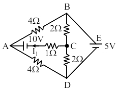
- 1The current flowing through the $1 \Omega$ resistor is $\frac{\mathrm{n}}{10} \ A. $ The value of $n$ is. . . . . . .View Solution
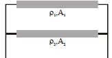
- 2Two conductors of same length are connected in parallel as shown in figure. Their cross-sectional areas $A_1$ and $A_2$ and their resistivities are ${\rho _1}$ and ${\rho _2}$ respectively. The equivalent resistivity of this combination isView Solution
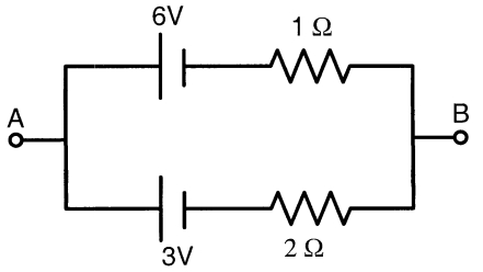
- 3Two batteries of different emfs and different internal resistances are connected as shown. The voltage across $A B$ in volts isView Solution
- 4A steady current $I$ flows through a wire of radius $r$, length $L$ and resistivity $\rho$. The current produces heat in the wire. The rate of heat loss in a wire is proportional to its surface area. The steady temperature of the wire is independent ofView Solution
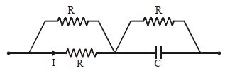
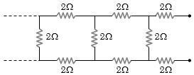
- 5View SolutionThe equivalent resistance of the following infinite network of resistances is
- 6A cylindrical conductor has uniform cross-section. Resistivity of its material increase linearly from left end to right end. If a constant current is flowing through it and at a section distance $x$ from left end, magnitude of electric field intensity is $E$, which of the following graphs is correctView Solution
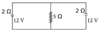
- 7In the arrangement shown in figure, the current through $5\,\Omega$ resistor is ............. $A$View Solution
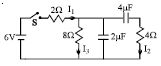
- 8In the circuit shown in the figure, the switch $S$ is initially open and the capacitor is initially uncharged. $ I_1, I_2$ and $I_3$ represent the current in the resistance $2\,\Omega , 4\,\Omega $ and $8\,\Omega$ respectively.View Solution
- 9Two electric bulbs whose resistances are in the ratio of $1 : 2$ are connected in parallel to a constant voltage source. The powers dissipated in them have the ratioView Solution
- 10View SolutionThe capacitor shown in fig. is in steady state. The energy stored in the capacitor is