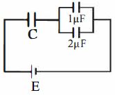
In the given circuit, charge $Q_2$ on the $2\ μF$ capacitor changes as $C$ is varied from $1\ μF$ to $3\ μF$. $Q_2$ as a function of '$C$' is given properly by: (figures are drawn schematically and are not to scale)
JEE MAIN 2015, Diffcult
Download our app for free and get started
From figure, $Q_{2}=\frac{2}{2+1} Q=\frac{2}{3} Q$
$Q = E\left( {\frac{{C \times 3}}{{C + 3}}} \right)$
$ {\therefore Q_{2}=\frac{2}{3}\left(\frac{3 C E}{C+3}\right)=\frac{2 C E}{C+3}}$
Therefore graph $d$ correctly dipicts.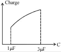

Download our appand get started for free
Experience the future of education. Simply download our apps or reach out to us for more information. Let's shape the future of learning together!No signup needed.*
Similar Questions
- 1View SolutionDielectric constant for metal is
- 2Three capacitors of capacitance $1\ \mu F$, $2 \ \mu F$ and $3\ \mu F$ are connected in series and a potential difference of $11 V$ is applied across the combination. Then, the potential difference across the plates of $1\ \mu F$ capacitor is......$V$View Solution
- 3The plates of a parallel plate capacitor are charged up to $100 \,volt$ . A $2 \,mm$ thick plate is inserted between the plates, then to maintain the same potential difference, the distance between the capacitor plates is increased by $1.6\, mm$. The dielectric constant of the plate is :-View Solution
- 4A parallel plate capacitor of capacitance $C$ has spacing $d$ between two plates having area $A$. The region between the plates is filled with $N$ dielectric layers, parallel to its plates, each with thickness $\delta=\frac{ d }{ N }$. The dielectric constant of the $m ^{\text {th }}$ layer is $K _{ m }= K \left(1+\frac{ m }{ N }\right)$. For a very large $N \left(>10^3\right)$, the capacitance $C$ is $\alpha\left(\frac{ K \varepsilon_0 A }{ d \;ln 2}\right)$. The value of $\alpha$ will be. . . . . . . .View Solution
[ $\in_0$ is the permittivity of free space]
- 5The capacitance of an air capacitor is $15\,\mu F$ the separation between the parallel plates is $6\,mm$. A copper plate of $3\,mm$ thickness is introduced symmetrically between the plates. The capacitance now becomes.........$\mu F$View Solution
- 6Two parallel plate capacitors have their plate areas $100 \,cm ^2$ and $500 \,cm ^2$ respectively. If they have the same charge and potential and the distance between the plates of the first capacitor is $0.5 \,mm$, then the distance between the plates of the second capacitor is ........ $cm$View Solution
- 7A fully charged capacitor has a capacitance $‘C’$. It is discharged through a small coil of resistance wire embedded in a thermally insulated block of specific heat capacity $‘s’$ and mass $‘m’$. If the temperature of the block is raised by ‘$\Delta T$’, the potential difference $‘V’$ across the capacitance isView Solution
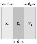
- 8The expression for the capacity of the capacitor formed by compound dielectric placed between the plates of a parallel plate capacitor as shown in figure, will be (area of plate $ = A$)View Solution
- 9After the switch shown in figure $A$ is closed, there is current $i$ through resistance $R$. Figure $B$ indicates current variation curves $a, b, c$ and $d$ for four sets of values of $R$ and capacitance $C$:View Solution
$(i)$ $R_0$ and $C_0$, $(ii)$ $2R_0$ and $C_0$,
$(iii)$ $R_0$ and $2C_0$, $(iv)$ $2R_0$ and $2C_0$.
Which set goes with which curve?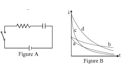
- 10In a parallel plate capacitor the separation between the plates is $3\,mm$ with air between them. Now a $1\,mm$ thick layer of a material of dielectric constant $2$ is introduced between the plates due to which the capacity increases. In order to bring its capacity to the original value the separation between the plates must be made......$mm$View Solution