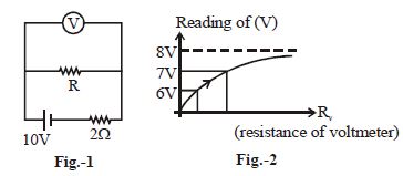
In the given figure $-1$, resistance of shown voltmeter is variable. Variation of whose reading with respect to its resistance is shown in figure $-2$. The value of $R$ is ............... $\Omega$
Medium


Download our appand get started for free
Experience the future of education. Simply download our apps or reach out to us for more information. Let's shape the future of learning together!No signup needed.*
Similar Questions
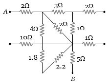
- 1Calculate the potential difference between, points $A$ and $B$ and current flowing in $10\,\Omega $ resistor in the part of network belowView Solution
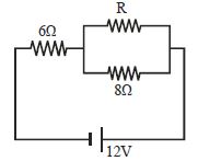
- 2In the circuit shown in figure, the power which is dissipated as heat in the $6\,\Omega $ resistor is $6\,W$. What is the value of resistance $R$ in the circuit? ................ $\Omega$View Solution
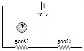
- 3A voltmeter of resistance $1000\,\Omega$ is connected across a resistance of $500\, \Omega$ in the given circuit. What will be the reading of voltmeter .............. $V$View Solution
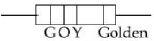
- 4A carbon resistor has colour strips as violet, yellow brown and golden. The resistance is .............. $\Omega$View Solution
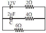
- 5Find the charge on the capacitor $C$ in the following circuit ............. $\mu C$View Solution
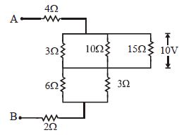
- 6What is the equivalent resistance between the points $A$ and $B$ of the network .................. $\Omega$View Solution
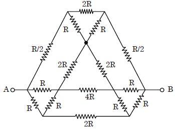
- 7For the shown circuit, find the effective resistance between the points $A$ and $B$.View Solution
- 8View SolutionA carbon resistance has a following colour code. What is the value of the resistance?
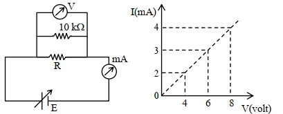
- 9To determine the resistance ($R$) of a wire, a circuit is designed below, The $V-I$ characteristic curve for this circuit is plotted for the voltmeter and the ammeter readings as shown in figure. The value of $\mathrm{R}$ is . . . . . . .$\Omega$View Solution
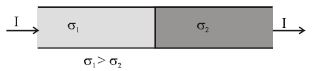
- 10Current $I$ is flowing through the two materials having electrical conductivities $\sigma_1$ and $\sigma_2$ respectively $(\sigma_1 > \sigma_2 )$ as shown in the figure. The total amount of charge at the junction of the materials isView Solution