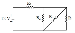
In the given figure $R_1=10 \Omega, R_2=8 \Omega, R_3=4 \Omega$ and $R_4=8 \Omega$. Battery is ideal with emf $12 \mathrm{~V}$. Equivalent resistant of the circuit and current supplied by battery are respectively.
JEE MAIN 2024, Diffcult


Download our appand get started for free
Experience the future of education. Simply download our apps or reach out to us for more information. Let's shape the future of learning together!No signup needed.*
Similar Questions
- 1In $n_e$ and $v_d$ be the number of electrons and drift velocity in a semiconductor. When the temperature is increasedView Solution
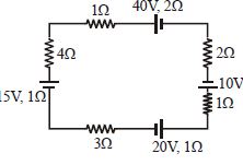
- 2View SolutionFind the current in the loop.
- 3View SolutionOhm's law fails in
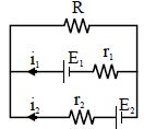
- 4View SolutionSee the electrical circuit shown in the adjoining figure. Which of the following equation is a correct equation for it
- 5View SolutionWhen electric bulbs of same power, but different marked voltage are connected in series across the power line, their brightness will be :
- 6A heater draws a current of $2\,A$ when connected to a $250\,V$ source. The rate of energy dissipation is ............. $W$View Solution
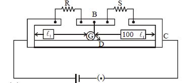
- 7In a meter bridge the point $D$ is neutral point as shown in the figure.View Solution
- 8The series combination of two batteries, both of the same emf $10 \mathrm{\;V},$ but different internal resistance of $20\; \Omega$ and $5\; \Omega,$ is connected to the parallel combination of two resistors $30\; \Omega$ and $\mathrm{R}\; \Omega .$ The voltage difference across the battery of internal resistance $20\; \Omega$ is zero, the value of $\mathrm{R}(\text { in } \Omega)$ isView Solution
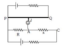
- 9Circuit for the measurement of resistance by potentiometer is shown. The galvanometer is first connected at point $A$ and zero deflection is observed at length $P J = 10\ cm$ . In second case it is connected at point $C$ and zero deflection is observed at a length $30\ cm$ from $P$ . Then the unknown resistance $X$ isView Solution
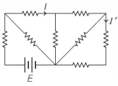
- 10Consider the following circuit shown below. All the resistors are identical. The ratio of $I / I^{\prime}$ isView Solution