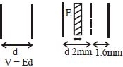
The plates of a parallel plate capacitor are charged up to $100\, volt$. A $2\, mm$ thick plate is inserted between the plates, then to maintain the same potential difference, the distance between the capacitor plates is increased by $1.6\, mm$. The dielectric constant of the plate is
Medium


Download our appand get started for free
Experience the future of education. Simply download our apps or reach out to us for more information. Let's shape the future of learning together!No signup needed.*
Similar Questions
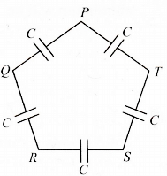
- 1Five capacitors, each of capacitance value $C$ are connected as shown in the figure. The ratio of capacitance between $P$ and $R$, and the capacitance between $P$ and $Q$, isView Solution
- 2A capacitor of $10\,\mu F$ charged up to $250\, volts$ is connected in parallel with another capacitor of $5\,\mu F$ charged up to $100\, volts$. The common potential is.....$V$View Solution
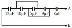
- 3Five capacitors together with their capacitances are shown in the adjoining figure. The potential difference between the points $A$ and $B$ is $60\, volt$. The equivalent capacitance between the point $A$ and $B$ and charge on capacitor $5 \mu F$ will be respectively:-View Solution
- 4Aparallel-plate capacitor is connected to a cell. Its positive plate $A$ and its negative plate $B $ have charges $+Q$ and $-Q$ respectively. A third plate $C$, identical to $A$ and $B$, with charge $+Q$, is now introduced midway between $ A$ and $B$, parallel to them. Which of the following are correct?View Solution
- 5A charge of $5\,C$ is given a displacement of $0.5\,m$. The work done in the process is $10\,J$. The potential difference between the two points will be.......$V$View Solution
- 6A charge $Q$ is distributed over three concentric spherical shell of radii $a, b, c (a < b < c)$ such that their surface charge densities are equal to one another. The total potential at a point at distance $r$ from their common centre, where $r < a$, would beView Solution
- 7A hollow metallic sphere of radius $R$ is given a charge $Q$. Then the potential at the centre isView Solution
- 8A capacitor of capacitance $C$ is charged to potential difference $V_0$. Now this capacitor is connected to an ideal inductor. When $25\%$ of energy of capacitor is transferred to inductor then at that time what will be potential difference across capacitorView Solution
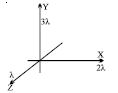
- 9The diagram shows three infinitely long uniform line charges placed on the $X, Y $ and $Z$ axis. The work done in moving a unit positive charge from $(1, 1, 1) $ to $(0, 1, 1) $ is equal toView Solution
- 10A condenser of $2\,\mu F$ capacitance is charged steadily from $0$ to $5\,C$. Which of the following graph represents correctly the variation of potential difference $(V)$ across it's plates with respect to the charge $(Q)$ on the condenser?View Solution