Two wires '$A$' and '$B$' of the same material have their lengths in the ratio $1 : 2$ and radii in the ratio $2 : 1$. The two wires are connected in parallel across a battery. The ratio of the heat produced in '$A$' to the heat produced in '$B$' for the same time is
Medium
Download our app for free and get started
(d) ${R_1} = \rho \frac{{{l_1}}}{{{A_1}}}$ and ${R_2} = \rho \frac{{{l_2}}}{{{A_2}}}$$ \Rightarrow $$\,\frac{{{R_1}}}{{{R_2}}} = \frac{{{l_1}}}{{{l_2}}}.\frac{{{A_2}}}{{{A_1}}} = \frac{{{l_1}}}{{{l_2}}}{\left( {\frac{{{r_2}}}{{{r_1}}}} \right)^2}$
Given $\frac{{{l_1}}}{{{l_2}}} = \frac{1}{2}$ and $\frac{{{r_1}}}{{{r_2}}} = \frac{2}{1}$ or $\frac{{{r_2}}}{{{r_1}}} = \frac{1}{2}$$ \Rightarrow $ $\frac{{{R_1}}}{{{R_2}}} = \frac{1}{8}$
$\therefore $ Ratio of heats $\frac{{{H_1}}}{{{H_2}}} = \frac{{{V^2}/{R_1}}}{{{V^2}/{R_2}}} = \frac{{{R_2}}}{{{R_1}}} = \frac{8}{1}$

Download our appand get started for free
Experience the future of education. Simply download our apps or reach out to us for more information. Let's shape the future of learning together!No signup needed.*
Similar Questions
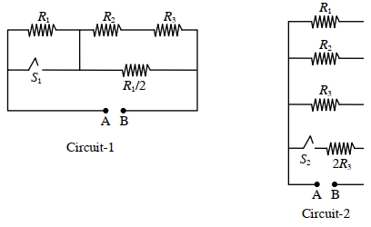
- 1In Circuit-$1$ and Circuit- $2$ shown in the figures, $R_1=1 \Omega, R_2=2 \Omega$ and $R_3=3 \Omega$. $P_1$ and $P_2$ are the power dissipations in Circuit-$1$ and Circuit-$2$ when the switches $S_1$ and $S_2$ are in open conditions, respectively. $Q_1$ and $Q_2$ are the power dissipations in Circuit-$1$ and Circuit-$2$ when the switches $S_1$ and $S_2$ are in closed conditions, respectively.View Solution
Which of the following statement($s$) is(are) correct?
$(A)$ When a voltage source of $6 V$ is connected across $A$ and $B$ in both circuits, $P_1$
$(B)$ When a constant current source of $2 Amp$ is connected across $A$ and $B$ in both circuits, $P_1>P_2$.
$(C)$ When a voltage source of $6 V$ is connected across $A$ and $B$ in Circuit-$1$, $Q_1>P_1$.
$(D)$ When a constant current source of $2 Amp$ is connected across $A$ and $B$ in both circuits, $Q_2$
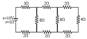
- 2In the circuit shown, the cell has $emf = 10\,V$ and internal resistance $= 1\, \Omega$ :-View Solution
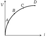
- 3Variation of current passing through a conductor as the voltage applied across its ends as varied is shown in the adjoining diagram. If the resistance $(R)$ is determined at the points $A$, $B$, $C$ and $D$, we will find thatView Solution
- 4The combination of two identical cells, whether connected in series or parallel combination provides the same current through an external resistance of $2 \,\Omega$. The value of internal resistance of each cell is ............ $\Omega$View Solution
- 5A filament bulb $(500 \,W,\,\, 100 \,V)$ is to be used in a $230\, V$ main supply. When a resistance $R$ is connected in series, it works perfectly and the bulb consumes $500\,W.$ The value of $R$ is .................. $\Omega$View Solution
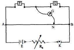
- 6In a meter bridge experiment resistances are connected as shown in the figure. Initially resistance $P\, = 4\,\Omega $ and the neutral point $N$ is at $60\,cm$ from $A$. Now an unknown resistance $R$ is connected in series to $P$ and the new position of the neutral point is at $80\,cm$ from $A$ . The value of unknown resistance $R$ isView Solution
- 7A cell can be balanced against $110\,\, cm$ and $100\,\, cm$ of potentiometer wire, respectively with and without being short circuited through a resistance of $10 \,\,\Omega$. Its internal resistance is ............... $\Omega$View Solution
- 8A cell of internal resistance $r$ is connected across an external resistance $n r$. Then the ratio of the terminal voltage to the emf of the cell isView Solution
- 9When the resistance of $9 \,\Omega$ is connected at the ends of a battery, its potential difference decreases from $40\, volt$ to $30\, volt$. The internal resistance of the battery is ............... $\Omega$View Solution
- 10In order to determine the $e.m.f.$ of a storage battery it was connected in series with a standard cell in a certain circuit and a current $I_1$ was obtained. When the battery is connected to the same circuit opposite to the standard cell a current $I_2$ flow in the external circuit from the positive pole of the storage battery was obtained. What is the $e.m.f$. $\varepsilon_1$ of the storage battery? The $e.m.f$. of the standard cell is $\varepsilon_2$.View Solution