Questions · Page 3 of 4

M.C.Q [1M]

MCQ 1011 Mark
In non-resonant circuit, what will be the nature of the circuit for frequencies higher than the resonant frequency?
  • A
    Resistive
  • B
    Capacitive
  • C
    Inductive
  • D
    None of these
Answer
  1. Inductive

Explanation:

At resonant frequency

$\text{X}_\text{L}=\text{X}_\text{C}=\Big(\omega\text{L}=\frac{1}{\omega\text{C}}\Big)$

At frequencies higher than resonance frequencies

$\text{X}_\text{L}>\text{X}_\text{C}$

i.e., behaviour is inductive.

View full question & answer
MCQ 1021 Mark
A coil of $10\text{mH}$ and $10\Omega$ resistance is connected in parallel to a capacitance of $0.1\mu\text{F}$ The impedance of the.
  • A
    $10^2\Omega$
  • B
    $10^4\Omega$
  • C
    $10^6\Omega$
  • D
    $10^8\Omega$
Answer
  1. $10^4\Omega$
View full question & answer
MCQ 1031 Mark
A solenoid of length 10cm, diameter 1cm, number of turns 500 with relative permeability of the core 2000, is connected to an ac source of frequency 50 Hz. Then, the reactance is.
  • A
    $\text{Zero}$
  • B
    $55\Omega$
  • C
    $105\Omega$
  • D
    $155\Omega$
Answer
  1. $155\Omega$

Explanation:

Inductance of the solenoid $=\text{L}=\frac{\mu\text{N}^2\text{A}}{1}=0.493\text{H}$

reactance of this solenoid $=\text{L}\omega=\text{L}2\pi\text{f}=155\Omega$

View full question & answer
MCQ 1041 Mark
An amplitude modulated (AM) radio operates at 550kHz to 1650kHz. If L is fixed and C is varied for tuning then minimum and maximum value of C is.
  • A
    C, 3C
  • B
    C, 6C
  • C
    C, 9C
  • D
    C, 12C
Answer
  1. C, 9C

Explanation:

$\frac{\text{f}_\text{max}}{\text{f}_\text{max}}=3$

$\therefore\frac{\sqrt{\text{LC}_\text{max}}}{\sqrt{\text{LC}_\text{min}}}=3$

$\frac{\text{C}_\text{max}}{\text{C}_\text{min}}=9$

${\text{C}_\text{min}}=\text{C}$

$\therefore{\text{C}_\text{max}}=\text{9C}$

View full question & answer
MCQ 1051 Mark
In an A.C. circuit the potential difference across an inductance and resistance joined in series are respectively 16V and 20V. The total potential difference across the circuit is.
  • A
    20.0V
  • B
    25.6V
  • C
    31.9V
  • D
    53.5V
Answer
  1. 25.6V

Explanation:

Potential difference across the circuit

$\text{V}=\sqrt{\text{V}^2_\text{R}+\text{V}^2_\text{L}}=\sqrt{20^2+16^2}=\sqrt{656}=25.6\text{V}$

View full question & answer
MCQ 1061 Mark
The power loss is less in transmission lines, when:
  • A
    Voltage is less but current is more
  • B
    Both voltage and current are more
  • C
    Voltage is more but current is less
  • D
    Both voltage and current are less
Answer
  1. Voltage is more but current is less

Explanation:

The power cables have some resistance. 

Power lost in the wires can be calculated as P = I2R with R as the resistance of the wires and I as the current that passes through them.

Power at the load is P = VI. 

From this one can see that if voltage is increased by say n times, then only $\frac{1}{\text{n}}$​ the current is required to deliver the same power. However, if $\frac{1}{\text{n}}$​ current is passed

on the same wires, only $\frac{1}{\text{n}^2}$ of the power will be lost.

View full question & answer
MCQ 1071 Mark
Symbol of Inductance in electric circuit is-
  • A

    Image
  • B

    Image
  • C

    Image
  • D

    Image
Answer
  1. Image

Explanation:

A is for resitance, B is for inductance, C is for a switch and D is for Galvanometer.

View full question & answer
MCQ 1081 Mark
For a series LCR circuit the power loss at resonance is : -
  • A
    $\frac{\text{V}^2}{\Big[\omega\text{L}-\frac{1}{\omega\text{C}}\Big]}$
  • B
    $\text{I}^2\text{L}\omega$
  • C
    $\text{I}^2\text{R}$
  • D
    $\frac{\text{V}^2}{\text{C}\omega}$
Answer
  1. $\text{I}^2\text{R}$
View full question & answer
MCQ 1091 Mark
In an oscillating system, a restoring force is a must. In an L-C circuit, the restoring force is provided by a/ an.
  • A
    inductor
  • B
    capacitor
  • C
    resistor
  • D
    both A and B
Answer
  1. inductor.
View full question & answer
MCQ 1101 Mark
The capacitance in an oscillatory LC circuit is increased by 1%. The change in inductance required to restore its frequency of oscillation is to.
  • A
    decrease it by 0.5%
  • B
    increase it by 1%
  • C
    decrease it by 1%
  • D
    decrease it by 2%
Answer
  1. decrease it by 1%
View full question & answer
MCQ 1111 Mark
The diagram given show the variation of voltage and current in an AC circuit. The circuit contains.
Image
  • A
    Only a resistor
  • B
    Only a pure inductor
  • C
    Only a capcacitor
  • D
    A capacitor and and inductor
Answer
  1. Only a pure inductor

Explantion:

The given circuit shows that the current lags the applied voltage. This is possible if the circuit has inductive element. So, the circuit contain a pure inductor.

View full question & answer
MCQ 1121 Mark
What is the range of the characteristic impedance of a coaxial cable?
  • A
    $\text{Between }150\Omega \text{ to } 600\Omega$
  • B
    $\text{Between }50\Omega \text{ to } 70\Omega$
  • C
    $\text{Between }0\Omega \text{ to } 50\Omega$
  • D
    $\text{Between }100\Omega \text{ to } 150\Omega$
Answer
  1. $\text{Between }50\Omega \text{ to } 70\Omega$

Explanation:

Characteristic impedance of a coaxial cable is $\text{Between }50\Omega \text{ to } 70\Omega$

View full question & answer
MCQ 1131 Mark
When the frequency of AC is doubled, the impedance of an LCR series circuit:
  • A
    is halved
  • B
    is doubled
  • C
    increases
  • D
    decreases
Answer
  1. increases
View full question & answer
MCQ 1141 Mark
Transformers are used:
  • A
    In DC circuits only.
  • B
    In AC circuits only.
  • C
    In both DC and AC circuits.
  • D
    Neither in DC nor in AC circuits.
Answer
  1. In AC circuits only.

Explanation:

Transformers are used in AC circuits only.

View full question & answer
MCQ 1151 Mark
A coil of negligible resistance is connected in series with a $90\Omega$ resistor across a 120 V, 60 Hz line. An ac voltmeter reads 90 V across the resistance, then the inductance of the coil is approximately.
  • A
    0.2 H
  • B
    0.3 H
  • C
    0.4 H
  • D
    0.7 H
Answer
  1. 0.2 H
View full question & answer
MCQ 1161 Mark
In an LCR circuit, capacitance is changed from C to 2C. For the resonant frequency to remain unchanged, the inductance should be changed from L to:
  • A
    4L
  • B
    2L
  • C
    $\frac{\text{L}}{2}$
  • D
    $\frac{\text{L}}{4}$
Answer
  1. $\frac{\text{L}}{2}$

Explanation:

Resonant frequency, $\text{f}_\text{r}=\frac{1}{2\pi\sqrt{\text{LC}}}$

As the frequency is unchanged so fr ​= fr′​

LC = L′C ′= L′(2C)

$\text{L}=\frac{\text{L}}{2}$

View full question & answer
MCQ 1171 Mark
In series combination of R, L, C with an A.C source at resonanace, if R = 20 ohm, then impedence Z of the combination is.
  • A
    20 ohm
  • B
    zero
  • C
    10 ohm
  • D
    400 ohm
Answer
  1. 20 ohm

Explanation:

We know at resonance, reactance (resistance due to inductor and capacitor) be zero (0).

At resonance, Impedance (Z) = Resistance (R)

Therefore, Z = 20 ohm

View full question & answer
MCQ 1181 Mark
If a capacitor is connected to two different A.C. generators, then the value of capacitive reactance is:
  • A
    directly proportional to frequency
  • B
    inversely proportional to frequency
  • C
    independent of frequency
  • D
    inversely proportional to the square of frequency
Answer
  1. inversely proportional to frequency

Explanation:

$\text{X}_\text{C}=\frac{1}{\omega\text{c}}$

$\therefore\text{X}_\text{C}\propto\frac{1}{\omega}$

View full question & answer
MCQ 1191 Mark
In R - L - C series circuit, the potential differences across each element is 20V. Now the value of the resistance alone is doubled, then P.D. across R, L and C respectively.
  • A
    20V, 10V, 10V
  • B
    20V, 20V, 20V
  • C
    20V, 40V, 40V
  • D
    10V, 20V, 20V
Answer
  1. 20V, 10V, 10V

Explanation:

Circuit is at resonance (VL = VC)

$\therefore$ circuit is purely resistance

Resistance is doubled, current in the circuit is half the initial value

$\therefore$ New current $\text{I′}=\frac{\text{I}}{2}$

$\therefore$ VR = 20V (equal to applied voltage earlier)

 VL = 10V

 VC = 10V

View full question & answer
MCQ 1201 Mark
If the rms current in a 50Hz ac circuit is 5A, the value of the current $\frac{1}{300}$ seconds after its value becomes zero is,
  • A
    $5\sqrt{2}\text{A}$
  • B
    $5\sqrt{\frac{3}{2}}\text{A}$
  • C
    $\frac{5}{6}\text{A}$
  • D
    $\frac{5}{\sqrt{2}}\text{A}$
Answer
  1. $5\sqrt{\frac{3}{2}}\text{A}$

Solution:

Key concept: Equation for i and V: Alternating current or voltage varying as sine function can be written as

$\text{i}=\text{i}_0\ \sin\omega\text{t}=\text{i}_0\ \sin2\pi\text{v t}=\text{i}_0\sin\frac{2\pi}{\text{T}}\text{t}$

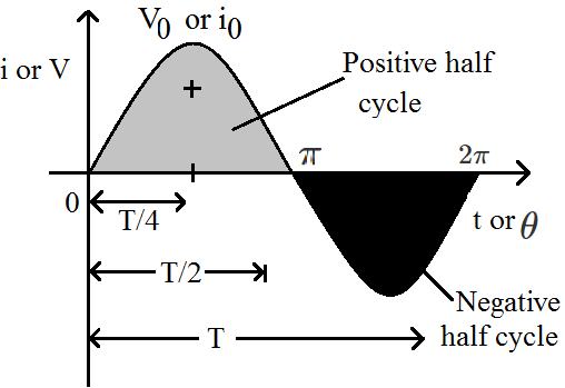
and $\text{V}=\text{V}_0\ \sin\omega\text{t}=\text{V}_0\ \sin2\pi\text{v t}=\text{V}_0\sin\frac{2\pi}{\text{T}}\text{t}$

where i and V are instantaneous values of current and voltage,

i0 and V0 are peak values of current and voltage

$\omega$ = Angular frequency in $\frac{\text{red}}{\text{sec}}$, v = Frequency in Hz and T = time period

Accoeding to the problem, f = 50Hz, Irms = 5A

$\text{t}=\frac{\text{I}}{300}\text{s}$

$\text{I}_0=\text{Peak value}=\sqrt{2}(\text{I}_\text{rms})=5\sqrt{2}$

$=5\sqrt{2}\text{A}$

From, $\text{I}=\text{I}_0\sin\omega\text{t}=5\sqrt{2}\sin2\pi\text{vt}=5\sqrt{2}\sin2\pi\times50\times\frac{1}{300}$

$=5\sqrt{2}\sin\frac{\pi}{3}=5\sqrt{2}\times\frac{\sqrt{3}}{2}=5\sqrt{\frac{3}{2}}\text{A}$

View full question & answer
MCQ 1211 Mark
A sinusoidal voltage $\text{V}=200\sin314\text{t}$ is applied to a $10\Omega$ resistor. Find the peak voltage.
  • A
    200V
  • B
    400V
  • C
    600V
  • D
    800V
Answer
  1. 200V

Explanation:

General sinusoidal voltage variation is given by:

$\text{V}=\text{V}_0\sin(\omega\text{t})$

Here, in this equation V0​ is peak voltage.

So, on comparing both equation we get:

$\text{V}_0=200\text{V},\omega=314$

View full question & answer
MCQ 1221 Mark
The reactance of a circuit is zero. It is possible that the circuit contains.
  • A
    an inductor and a capacitor
  • B
    an inductor but no capacitor
  • C
    a capacitor but no inductor
  • D
    neither an inductor nor a capacitor
Answer
  1. neither an inductor nor a capacitor

Explanation:

Answer: A an inductor and a capacitor, B neither an inductor nor a capacitor
Reactance in electrical and electronic systems is the opposition of a circuit element to a change of electric current or voltage.Ideally a resistor has zero reactance.
Therefore in a circuit, reactance can be zero either if there are no inductors and capacitors in the circuit, or the individual reactance of inductors and capacitors cancel each other, making net reactance zero.

View full question & answer
MCQ 1231 Mark
In LCR series AC circuit.
  • A
    If R is increased current will decrease.
  • B
    If L is increased current will decrease.
  • C
    If C is increased current will increase.
  • D
    If C is increased current will decrease.
Answer
  1. If R is increased current will decrease.

Explanation:

$\text{I}=\frac{\text{V}}{\text{Z}}=\frac{\text{V}}{\sqrt{\text{R}^2\Big(\omega\text{L }\sim}\frac{1}{\omega\text{C}}\Big)^2}$

By increasing R, current will definitely decrease by change in L or C, current may increase or decrease.

View full question & answer
MCQ 1241 Mark
An alternating current is given by $\text{i}=\text{i}_1\cos\omega\text{t}+\text{i}_2\sin\omega\text{t}.$ The rms current is given by:
  • A
    $\frac{\text{i}_1+\text{i}_2}{\sqrt{2}}$
  • B
    $\frac{|\text{i}_1+\text{i}_2|}{\sqrt{2}}$
  • C
    $\sqrt{\frac{\text{i}_1^2+\text{i}_2^2}{2}}$
  • D
    $\sqrt{\frac{\text{i}_1^2+\text{i}_2^2}{\sqrt{2}}}$
Answer
  1. $\sqrt{\frac{\text{i}_1^2+\text{i}_2^2}{2}}$

Explanation:

$\text{i}=\text{i}_1\cos\omega\text{t}+\text{i}_2\sin\omega\text{t}$

$\text{I}_\text{rms}=\frac{\int\limits_0^\text{T}\text{I}^2\text{dt}}{\int\limits_0^\text{T}\text{dt}}$

if $\text{I}=\cos\omega\text{t}$

$\text{I}_\text{rms}^2=\frac{\text{I}_0^2}{2}$

$\text{i}=\text{i}_1\cos\omega\text{t}+\text{i}_2\sin\omega\text{t}$

Than $\text{i}_\text{rms}^2=\frac{\text{i}_1^2}{2}+\frac{\text{i}_2^2}{2}$

$\text{i}_\text{rms}=\sqrt{\frac{\text{i}_1^2+\text{i}_2^2}{2}}$

View full question & answer
MCQ 1251 Mark
In the following diagram, the value of emf of A.C. source will be:
Image
  • A
    $40\text{V}$
  • B
    $40\sqrt{2}\text{V}$
  • C
    $\frac{40}{\sqrt2}\text{V}$
  • D
    $160\text{V}$
Answer
  1. $40\sqrt{2}\text{V}$

Explanation:

$\text{E}_\text{rms}=\sqrt{\text{V}^2_\text{R}+(\text{V}_\text{L}-\text{V}_\text{c})^2}$

$=\sqrt{40^2+(40-80)^2}$

$=\sqrt{40^2+40^2}$

$=40\sqrt{2}\text{V}$

View full question & answer
MCQ 1261 Mark
In the given circuit what is the potential drop across resistance?
Image
  • A
    40 V
  • B
    80 V
  • C
    120 V
  • D
    zero
Answer
  1. 120 V

Explanation:

At resonance the voltage across L and C are same but opposite.

So, at resonance $\mid\text{V}_\text{L}\mid=\mid\text{V}_\text{C}\mid$

$\therefore\text{V}_\text{R}=\text{V}_\text{app}=120\text{V}$

View full question & answer
MCQ 1271 Mark
The power loss in an AC circuit can be minimized by.
  • A
    Decreasing resistance and increasing inductance
  • B
    Decreasing inductance and increasimg resistance
  • C
    Increasing both inductance and resistance
  • D
    Decreasing both inductance and resistance
Answer
  1. Decreasing resistance and increasing inductance

Explanation:

In an AC circuit, power loss can be minimized by decreasing in resistance and by increasing in inductance.

View full question & answer
MCQ 1281 Mark
For the circuit shown in the Figure, the current through the inductor is 0.9 A while the current through the condenser is 0.4 A.
Image
  • A
    current drawn from generator I = 1.13 A
  • B
    $\omega=\frac{1}{(1.5\text{L.C})}$
  • C
    I = 0.5 A
  • D
    I = 0.6 A
Answer
  1. I = 0.5 A

Explantion:

The current in inductor and capacitor is always at an phase difference of 180°

for V $=\text{V}_\text{o}\sin\omega\text{t}$

Capacitor, $\text{i}=\text{i}_\text{o}\sin(\omega\text{t}-\frac{\pi}{2})$

Capacitor, $\text{i}=\text{i}_\text{o}\sin(\omega\text{t}+\frac{\pi}{2})$

So, the current from both branches will be 0.9 + (-0.4) = 0.5A

View full question & answer
MCQ 1291 Mark
When a voltage measuring device is connected to AC mains, the meter shows the steady input voltage of 220V. This means,
  • A
    Input voltage cannot be AC voltage, but a DC voltage.
  • B
    Maximum input voltage is 220V.
  • C
    The meter reads not v but < v2 > and is calibrated to read $\sqrt{<\text{v}^2>}$.
  • D
    The pointer of the meter is stuck by some mechanical defect.
Answer
  1. The meter reads not v but < v2 > and is calibrated to read $\sqrt{<\text{v}^2>}$.​​​​​​​
View full question & answer
MCQ 1301 Mark
With increase in frequency of an A.C. supply, the inductive reactance.
  • A
    decreases
  • B
    increases directly with frequency
  • C
    increases as square of frequency
  • D
    decreases inversely with frequency
Answer
  1. increases directly with frequency

Explanation:

The inductive reactance $\text{Xl}=\omega\text{L}$

Hence, $\text{X}_1\propto\omega$

As frequency increases $\rightarrow\omega$

Therefore, inductive reactance increases with frequency.

View full question & answer
MCQ 1311 Mark
In an LCR circuit the capacitance is made $\frac{1^\text{th}}{4}$ then what should be the change in inductance that the circuit remains in resonance again?
  • A
    8 times
  • B
    $\frac{1}{2}\text{times}$
  • C
    2 times
  • D
    4 times
Answer
  1. 4 times

Explanation:

$\text{f}_0=\frac{1}{2\pi\sqrt{\text{LC}}}.$

View full question & answer
MCQ 1321 Mark
In an LCR circuit inductance is changed from L to $\frac{\text{L}}{2}.$ To keep the same resonance frequency, C should be changed to.
  • A
    $2\text{C}$
  • B
    $\frac{\text{C}}{2}$
  • C
    $4\text{C}$
  • D
    $\frac{\text{C}}{4}$
Answer
  1. $2\text{C}$

Explanation:

Resonance frequency, $(\text{f})=\frac{1}{2\pi\sqrt{\text{LC}}}$

For f to be constant the product LC must be constant.

So, if we half the value of inductance then the value of capacitance must be doubled.

C should be changed to 2C.

View full question & answer
MCQ 1331 Mark
In a L - C - R circuit, as the frequency of an alternating current increases the impedance of the circuit.
  • A
    increases continuously.
  • B
    decreases continuously.
  • C
    remains constant.
  • D
    None of these.
Answer
  1. None of these.

Explanation:

Impedance first decreases then increases. At resonance frequency Z is minimum.

View full question & answer
MCQ 1341 Mark
A capacitor acts as an infinite resistance for:
  • A
    DC.
  • B
    AC.
  • C
    DC as well as AC.
  • D
    Neither AC nor DC.
Answer
  1. DC.

Explanation:

$\text{X}_\text{C}\frac{1}{\omega\text{C}}=\frac{1}{0\times\text{C}}$ $\bigg\{\text{in}\stackrel{{\text{DC}}}{{\omega = 0 }}\bigg\}$

$=\infty$

View full question & answer
MCQ 1351 Mark
Current in the circuit is wattless, if.
  • A
    Inductance in the circuit is zero
  • B
    Resistance in the circuit is zero
  • C
    Current is alternating
  • D
    Resistance and inductance both are zero
Answer
  1. Resistance in the circuit is zero

Explanation:

Current in the circuit is wattless, 

Because power = i2R, if R = 0, then P = 0.

View full question & answer
MCQ 1361 Mark
The frequency of A.C mains in India is.
  • A
    30Hz
  • B
    50Hz
  • C
    60Hz
  • D
    120Hz
Answer
  1. 50Hz

Explanation:

In India, the AC mains supply is referred to as single-phase alternating current and corresponds to a voltage of 230 V at a frequency of 50Hz, similar to most European countries. Whereas in the USA, AC mains supply uses 60Hz.

View full question & answer
MCQ 1371 Mark
The phase difference between alternating emf and current in a purely capacitive circuit will be.
  • A
    $\text{zero}$
  • B
    $\pi$
  • C
    $-\frac{\pi}{2}$
  • D
    $\frac{\pi}{2}$
Answer
  1. $-\frac{\pi}{2}$

Explanation:

In a purely capacitive circuit, current leads the voltage by $-\frac{\pi}{2}$

View full question & answer
MCQ 1381 Mark
An inductor coil of some resistance is connected to an AC source. Which of the following quantities have zero average value over a cycle?
  • A
    Current.
  • B
    Induced emf in the inductor.
  • C
    Joule heat.
  • D
    Magnetic energy stored in the inductor.
Answer
  1. Current.
  2. Induced emf in the inductor.

Explanation:

$\text{I}=\text{I}_0\sin\omega\text{t}$

Average value of current over a cycle = 0

$\text{V}=\text{V}_0\cos\omega\text{t}$

$=\text{V}_0\sin\bigg(\omega\text{t}+{\frac{\pi}{2}}\bigg)$

Average value of induced emf in inductor over a cycle = 0.

View full question & answer
MCQ 1391 Mark
A resistor and a capacitor are in series across a 20V ac source. Circuit impedance is $4.33\text{k}\Omega$ Current flow in the circuit is.
  • A
    9.2mA
  • B
    92mA
  • C
    4.6mA
  • D
    460mA
Answer
  1. 4.6mA

Explanation:

Voltage of the source V = 20 volts

$\text{Z}=4.33\text{k}\Omega=4.33\times10^3\Omega$

Thus current in the circuit $\text{I}=\frac{\text{V}}{\text{Z}}$

$\therefore\text{I}=\frac{20}{4.33\times10^3}=4.6\times10^{-3}\text{A}$

$\Rightarrow\text{I}=4.6\text{mA}$

View full question & answer
MCQ 1401 Mark
When the rms voltages VL​, VC​ and VR​ are measured respectively across the inductor L, the capacitor C and the resistor R in a series LCR circuit connected to an AC source, it is found that the ratio VL ​: VC ​: VR​ = 1 : 2 : 3. If the rms voltage of the AC source is 100 V, then VR​ is close to:
  • A
    50V
  • B
    70V
  • C
    90V
  • D
    100V
Answer
  1. 90V
View full question & answer
MCQ 1411 Mark
An a.c. supply of 100 volts is applied to a capacitor of capacitance 20 μ F. If the current in the circuit is 0.628 A, the frequency of a.c. must be.
  • A
    50 Hz
  • B
    60 Hz
  • C
    25 Hz
  • D
    40 Hz
Answer
  1. 50 Hz

Explanation:

$\text{Y}=100\text{V, C}=2\mu\text{F}=20\times10^{-6}$

$\text{I}=0.628\text{A,v}=?$

$\text{X}_\text{C}=\frac{\text{V}}{\text{I}}=\frac{100}{0.628}$

$\Rightarrow\frac{1}{2\pi\text{vC}}=\frac{100}{0.628}$

$\text{v}=\frac{0.628}{100\times2\pi\text{C}}$

$=50\text{ Hz}$

View full question & answer
MCQ 1421 Mark
When the frequency of the source voltage decreases, the impedance of a parallel RC circuit.
  • A
    increases
  • B
    decreases
  • C
    does not change
  • D
    decreases to zero
Answer
  1. increases

Explanation:

When the frequency of the source voltage decreases, the impedance of a parallel RC circuit will increase.

View full question & answer
MCQ 1431 Mark
The angular frequency of an AC source is $\frac{10\text{radian}}{\text{sec}}$ The reactance of $1\mu\text{F}$ capacitor will be.
  • A
    $10^4\Omega$
  • B
    $10^2\Omega$
  • C
    $10^1\Omega$
  • D
    $10^5\Omega$
Answer
  1. $10^5\Omega$

Explanation:

$\text{Reactance}=\frac{1}{\text{C}\omega}\Omega$

$=\frac{1}{10^{-6}\times10}=\frac{1}{10^{-5}}$

$=10^5\Omega$

View full question & answer
MCQ 1441 Mark
The simplest type of AC voltage or current is the one which.
  • A
    Varies exponentially
  • B
    Varies sinusoidally
  • C
    Varies linearly
  • D
    Does not vary uniformly
Answer
  1. Varies sinusoidally

Explanation:

AC voltage or current can be of any form, but the simplest type is a sine wave because any periodic wave can be represented as a combination of sine waves.

View full question & answer
MCQ 1451 Mark
The output of a step-down transformer is measured to be 24V when connected to a 12 watt light bulb. The value of the peak current is:
  • A
    $\frac{1}{\sqrt{2}}\text{A}.$
  • B
    $\sqrt{2}\text{A}.$
  • C
    $2\text{A}.$
  • D
    $2\sqrt{2}\text{A}.$
Answer
  1. $\frac{1}{\sqrt{2}}\text{A}.$

Solution:

Key concept: It decreases voltage and increases current

VS < VP

NS > NP

ES < EP

iS > iP

RS < RP

tS > tP

k < l

According to the problem output/secondary voltage VS = 24V

Power associated with secondary PS = 12W

$\text{I}_\text{S}=\frac{\text{P}_\text{S}}{\text{V}_\text{S}}=\frac{12}{24}=0.5\text{A}$

Amplitude of the current in the secondary winding

$\text{I}_0=\text{I}_\text{S}\sqrt{2}$

$=(0.5)(1.414)=0.707=\frac{1}{\sqrt{2}}\text{A}$

View full question & answer
MCQ 1461 Mark
In an L - C - R circuit the value of XL​, XC​ and R are $300\Omega,200\Omega$, and $100\Omega$ respectively. The total impedance of the circuit will be.
  • A
    $600\Omega$
  • B
    $200\Omega$
  • C
    $141\Omega$
  • D
    $310\Omega$
Answer
  1. $141\Omega$

Explanation:

Total impedance = R + j(XL​ - XC​)

$=100+\text{j}100$

$=100\sqrt{2}\measuredangle45$

$=141\measuredangle45$

View full question & answer
MCQ 1471 Mark
An alternating voltage $\text{E}=50\sqrt{2}\sin(100\text{t})$ V is connected to a $1\mu\text{F}$ capacitor through an ac ammeter. What will be the reading of the ammeter?
  • A
    $10\text{mA}$
  • B
    $5\text{mA}$
  • C
    $5\sqrt{2}\text{mA}$
  • D
    $10\sqrt{2}\text{mA}$
Answer
  1. $5\text{mA}$

Explanation:

$\text{X}_\text{C}=\frac{1}{\text{C}\omega}=10000\Omega$

ammeater reading $=\text{I}_\text{rms}=\frac{\text{V}_\text{rms}}{\mid\text{jX}_\text{c}\mid}=\frac{50}{10000}=5\text{mA}$

View full question & answer
MCQ 1481 Mark
The capacitive reactance in an AC circuit is.
  • A
    effective resistance due to capacity
  • B
    effective wattage
  • C
    effective voltage
  • D
    None of these
Answer
  1. effective resistance due to capacity

Explanation:

Capacitive reactance in an A.C circuit is: $\text{X}_\text{C}=\frac{1}{\omega\text{C}}\text{ohm}$

where, C is the capacitance of capacitor and $\omega=2\pi\text{rn}$ (n is the frequency of A.C source)

View full question & answer
MCQ 1491 Mark
In a circuit inductance L and capacitance C are connected as shown in figure. A1​ and A2​ are ammeters.
When key K is pressed to complete the circuit, then just after closing key (K), the readings of A1​ and A2​ will be.
Image
  • A
    zero in both A1​ and A2
  • B
    maximum in both A1​ and A2​
  • C
    zero in A1​ and maximum in A2
  • D
    maximum in A1​ and zero in A2​
Answer
  1. maximum in A1​ and zero in A2​

Explanation:

Initially there is no D.C current in inductive circuit and maximum D.C current is in capacitive current. Hence, the current is zero in A2​ and maximum in A1​

View full question & answer
MCQ 1501 Mark
In the following circuit, the values of current flowing in the circuit at f = 0 and $\text{f}=\infty$ will respectively be.
Image
  • A
    8A and 0A
  • B
    0A and 0A
  • C
    8A and 8A
  • D
    0A and 8A
Answer
  1. 0A and 0A

Explanation:

In a LCR circuit current at t = 0 is zero because inductor does not allow flow of current,

and at t = ∞ also current is zero because capacitor does not allow flow of current.

View full question & answer