Question 13 Marks
Explain the principle, construction, working and application of moving coil galvanometer.
Answer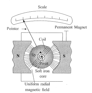
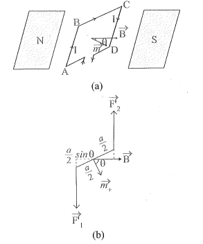
→Figure shows a moving coil galvanometer.
• Principle :
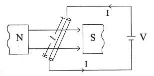
→A torque is exerted on the current carrying coil placed in uniform magnetic field.
• Construction :
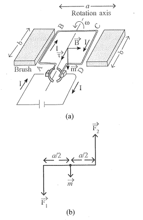
→A thin copper wire is wounded on rectangular frame placed between two cylindrical permanent magnets as shown in the figure. The coil is arranged so it can rotate freely.
→A small cylinder of soft iron is placed on the axis of the coil, without touching the coil, to produce a uniform radial magnetic field.
→When current is passed through the coil a torque acts on it and it deflects. The steady deflection of coil is indicated by a pointer attached with it.
• Working :
→When a current flows through the coil, a torque acts on it, causing it to deflect.
→If the area vector of the coil makes an angle $\theta$ with the magnetic field, torque acting on coil is
$\tau= NIBA \sin \theta$
→Due to the radial magnetic field, the angle between $\overrightarrow{ A }$ and $\overrightarrow{ B }$ will always be $90^{\circ}$.
$\therefore \tau=\text { NIBA }$
→Due to the deflection of the coil, the restoring torque is produced in the spring which is directly proportional to the deflection of the coil $(\phi)$
$\therefore$ Restoring torque $\tau^{\prime}=k \phi$
Where, $k=$ torsional constant of the spring.
→ For steady deflection, from equation (1) \& (2)
$\begin{aligned}
\tau^{\prime} & =\tau \\
k \phi & =\text { NIAB } \\
\therefore \phi & =\left(\frac{ BAN }{k}\right) \cdot I \\
\therefore \phi & \propto I \quad(\because B , A , N , K \text { are constant })
\end{aligned}$
→Thus, the deflection of the coil is directly proportional to the current.
→Uses : Galvanometer is used to detect the presence of current in the circuit.
→To measure small electric currents (of the order $10^{-6} A$ )
→Using galvanometer, ammeter and voltmeter can be constructed.
View full question & answer→→Figure shows a moving coil galvanometer.
• Principle :
→A torque is exerted on the current carrying coil placed in uniform magnetic field.
• Construction :
→A thin copper wire is wounded on rectangular frame placed between two cylindrical permanent magnets as shown in the figure. The coil is arranged so it can rotate freely.
→A small cylinder of soft iron is placed on the axis of the coil, without touching the coil, to produce a uniform radial magnetic field.
→When current is passed through the coil a torque acts on it and it deflects. The steady deflection of coil is indicated by a pointer attached with it.
• Working :
→When a current flows through the coil, a torque acts on it, causing it to deflect.
→If the area vector of the coil makes an angle $\theta$ with the magnetic field, torque acting on coil is
$\tau= NIBA \sin \theta$
→Due to the radial magnetic field, the angle between $\overrightarrow{ A }$ and $\overrightarrow{ B }$ will always be $90^{\circ}$.
$\therefore \tau=\text { NIBA }$
→Due to the deflection of the coil, the restoring torque is produced in the spring which is directly proportional to the deflection of the coil $(\phi)$
$\therefore$ Restoring torque $\tau^{\prime}=k \phi$
Where, $k=$ torsional constant of the spring.
→ For steady deflection, from equation (1) \& (2)
$\begin{aligned}
\tau^{\prime} & =\tau \\
k \phi & =\text { NIAB } \\
\therefore \phi & =\left(\frac{ BAN }{k}\right) \cdot I \\
\therefore \phi & \propto I \quad(\because B , A , N , K \text { are constant })
\end{aligned}$
→Thus, the deflection of the coil is directly proportional to the current.
→Uses : Galvanometer is used to detect the presence of current in the circuit.
→To measure small electric currents (of the order $10^{-6} A$ )
→Using galvanometer, ammeter and voltmeter can be constructed.