Questions

[5 Mark Question Answer]

🎯

Test yourself on this topic

13 questions · timed · auto-graded

Question 15 Marks
State Lenz's Law.
Answer
Lenz's law: It is stated that the direction of induced e.m.f. is always in such direction that it opposes the change in magnetic flux.
$
e=\frac{d \varphi}{d t}
$
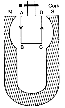
Consider a rectangular metal coil PQRS. Let ' $L$ ' be the length of the coil. It is placed in a partly magnetic field ' $B$ '. the direction of magnetic field is perpendicular to paper and into the paper. The ' $x$ ' part of the coil is in magnetic field at instant $t$. If the coil is moved towards right with a velocity $v=d x / d t$ with help of external agent like hand. The magnetic flux through the coil is $\Phi=B A=B L x \therefore \Phi=B L x$----(1) There is relative motion of a current through the coil. Let ' $i$ ' be current through the coil.

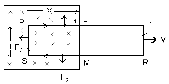
Three forces acts on the coil .
$F _1$ on conductor PL $\therefore F 1=$ Bix, vertically upward.
$F _2$ on conductor MS $\therefore F 2=$ Bix, vertically downward.
$F _3$ on conductor SP $\therefore F 3=$ BiL towards left. $F_1 \& F_2$ are equal and opposite and also in a same lines. They will cancel each other, $F_3$ is a resultant force. The external agent has to do work against this force.
$\therefore F 3=- Bil - ve$ sign indicates that force is opposite to $dx$.
If $dx$ is displacement in time $dt$, then work done $dw = F 3 dx$
$
\therefore dw =- \text { BiL } dx
$
This power is an electrical energy 'ei' where ' $e$ ' is an induced e.m.f.
$
\begin{aligned}
& \therefore e i=-\frac{B i l d x}{d t} \\
& \therefore e=-\frac{B L d x}{d t}
\end{aligned}
$
This power is an electrical energy 'ei' where ' $e$ ' is an induced e.m.f.
$
\begin{aligned}
& \therefore e i=-\frac{B i l d x}{d t} \\
& \therefore e=-\frac{B L d x}{d t}
\end{aligned}
$
$
\therefore e=-B L v
$
$\therefore e=-\frac{d}{d t}(B L x)$
$\therefore=e=-\frac{d \varphi}{d t}$ from eq (1)
View full question & answer
Question 25 Marks
What is an electromagnet? List any two uses.
Answer
The magnetic field produced due to the current flowing in a coil or a solenoid can be used to magnetize a material like soft iron temporarily. The insulated copper wire is wrapped on a soft iron piece. When current is passed through the coil using a battery and a key the iron piece behaves like a bar magnet as long as the current is being passed. Such a magnet is called an electromagnet.

Uses of Electromagnet :

1) Magnets are used inside TVs, Sound speakers, and radios.
2) Magnets are used inside a generator to transform mechanical energy to electrical energy

View full question & answer
Question 35 Marks
State Fleming's left hand rule.
Answer

According to this rule, stretch the thumb, forefinger and middle finger of your left hand such that they are mutually perpendicular. If the first finger points in the direction of magnetic field and the second finger in the direction of the current, then the thumb will point in the direction of motion of the conductor or the force acting on the conductor.
View full question & answer
Question 45 Marks
A current-carrying solenoid is suspended so as to freely rotate in a horizontal plane. State in what direction will it rest. Give a reason for your answer.

or

When a solenoid that is carrying current is freely suspended, it comes to rest in a particular direction. Why does this happen?

Answer
The current carrying solenoid when suspended freely, will rest along the N-S direction. The reason is that it will behave like a bar magnet, with N polarity at one face of solenoid and S polarity at the other face, depending upon the direction of current in the solenoid.
Current carrying solenoid behaves like a bar magnet. At end in which direction of current is anticlockwise, behaves as north pole and where current is in clockwise direction behaves as south pole. Therefore on suspending it freely, set it self in North-South direction as bar magnet does.
View full question & answer
Question 55 Marks
A flat coil of wire rotates at a constant speed about an axis perpendicular to a uniform magnetic field. Draw a graph to show how the induced e.m.f. varies relative to the positions of the coil during its one complete rotation. At what position of the coil, the e.m.f. has the maximum value?
Answer

Figure below shows the variation in induced e.m.f. relative to various positions of coil, during its one complete rotation.
The e.m.f. is maximum when the coil is with its plane parallel to the magnetic field.

V = Coil vertical
H = Coil Horizontal
View full question & answer
Question 65 Marks
State and illustrate the rule used for finding the polarity of the faces of a circular coil.
Answer
For finding the polarity of the two faces of a current-carrying circular coil, the following rule applies:


When an observer, looking at the circular coil, finds the current to be flowing in the anti-clockwise direction, then the face of the coil behaves like the N-pole of the equivalent magnet. On the other hand, if the current is seen to flow in the clockwise direction, then the face of the coil behaves like the S-pole of the equivalent magnet.
View full question & answer
Question 75 Marks
(i) Draw a clear labelled diagram of an electric bell.
(ii) Explain in brief, its working.
(iii) What material is used for the core of an electric bell? State the reason.
Answer

ii) An electric bell is one of the most common applications of an electromagnet.
Construction and wiring: An electric bell shown in above fig. The main parts of the bell are:
  1. A horse-shoe electromagnet M, having iron core,
  2. Soft iron armature A,
  3. A hammer H,
  4. A gong G,
  5. A metallic spring strip SS,
  6. An adjusting screw SS,
  7. A switch (or bell-push) K, and
  8. A battery.
Working and function of each part:
The working of an electric bell is based on the magnetic effect of current. When the electric circuit is closed by pressing the switch K, the current flows through the coil CC and the core of electromagnet gets magnetized and therefore it attracts the armature A as shown A, the hammer H strikes the gong G and the bell rings.
At the moment, when the armature, due to attraction, moves towards the electromagnet, the connection between the strip SS and the screw S’ breaks which stops the flow of current in the circuit. Consequently, the electromagnet loses magnetism (i.e.r it gets demagnetized) and the armature A flies back to its original position due to the spring effect of the strip SS. Now the armature again touches the screw S’, resulting in the flow of current in the circuit. The electromagnet regains its magnetism and the armature A is again attracted, so the hammer H strikes the gong G again.
This process of make and break of the circuit goes on the hammer strikes the gong repeatedly and the bell rings so long as the switch K is kept pressed.
(iii) The core of the electromagnet is made of soft iron because: Firstly, it increases the intensity of the magnetic field of the electromagnet and secondly it easily get demagnetized when no current flows in the turns of the coil of insulated copper wire wound over the core, thus helping in the smooth working of the electric bell.
View full question & answer
Question 85 Marks
The power supply to the primary coil of a transformer is 200 W. Find
(i) Current in primary coil if the e.m.f. supply to it is equal to 220V.
(ii) The number of turns in the primary coil is equal to 80 and that in secondary is 800. What is the transformation ratio?
(iii) Name the type of transformer.
(iv) What will be the output voltage?
(v) What is the current in the secondary coil for an ideal transformer?
(vi) What is the output power?
(vii) Is output and input power equal?
(viii) Compare the current flowing in a secondary coil and in a primary coil.
Answer
(i) $P ($ Power $)=200 W = VI = E _{ p } \times I _{ p }$
$\therefore P=200=200 \times I_p$
$\therefore$ Current in the primary coil $=\frac{200}{220}$
$I_p=0.909 A$
(ii)
Transformation ratio $\frac{ E _{ s }}{ E _{ p }}=\frac{ N _{ s }}{ N _{ p }}=\frac{800}{80}=10$
(iii) It is a step up transformer.
(iv) Using $\frac{E_s}{E_p}=\frac{N_s}{N_p}=10$
$
\therefore \frac{ E _{ s }}{200}=10
$
$
\therefore E _{ S }=2200 V
$
(v) Using $E_p \times I_p=2200 \times I_S$
$
\begin{aligned}
& \therefore 200=2200 \times I _{ S } \\
& \therefore I _{ S }=\frac{2}{22}=0.090 A
\end{aligned}
$
(vi) Outpput power $= E _{ S } \times I _{ S }=\frac{2200 \times 0.0909}{100}=200 W$
(vii) Yes, It is equal, because it is an ideal transformer, for an ideal transformer
$
\text { Efficiency }=\eta=\frac{\text { Outout power }}{\text { Input power }}=1 \text { or } 100 \%
$
i.e., there is no energy loss due to any cause.
(viii) $I_S=0.0909 A$ and $I_p=0.909 A$
Less current flows through the secondary coil than in the primary coil because it is a step-up transformer.
View full question & answer
Question 95 Marks
Copy the given diagram of a transformer and complete it. Name the parts A and B. Name the part you have drawn to complete the diagram. What is the material of this part? Is this transformer a step-up or step-down? Give reason.
Answer
The completed diagram is given below:


Part A is called primary coil. Part B is called a secondary coil.
The part drawn is called core.
The material of the core is soft iron.
(i) This transformer is step-down since it has more turns in the primary coil than in secondary coil.
(ii) A step-up transformer has more turns in secondary coil as compared to that in the primary coil, while a step-down transformer has more turns in primary coil as compared to that in secondary coil.
(iii) In a step-up transformer the wire in the primary coil is thicker as compared to that in secondary coil, while in a step-down transformer the wire in secondary coil is thicker as compared to that in primary coil.
View full question & answer
Question 105 Marks
The given figures $1$ to $3$ show the working of a simple $A.C$. generator. Study the diagrams and answers of the following questions.


(i) State and explain the principle underlying the working of a simple generator.
(ii) Where is the loop of wire placed?
(iii) What happens when the loop is rotated?
(iv) Indicate the direction of the current flow through the wire for the first half of the turn (in first figure). Name and state the rule used in finding the direction of the current.
(v) Indicate the direction of the current for the case shown in second figure.
(vi) Indicate the direction of current in the outer circuit (i.e., electric bulb) in first and third figure.
(vii) What type of current is shown in the above diagrams? Explain.
Answer
(i) The generator works on the principle of Electromagnetic Induction. Whenever the flux passing through a closed circuit changes, e.m.f. is induced in it and a current begins to flow. Its direction is given by Fleming's Right Hand Rule or Lenz Law. As long as the loop is moving within the magnetic field an electric current will flow.(ii) The loop of wire is placed between the two poles of a ' $U$ '-shaped magnet.
(iii) When the loop of wire is rotated between the two poles of a ' $U$ '-shaped magnet an electric current flows through the wire.
(iv) As rotation of the coil is the clockwise direction and the direction of magnetic field is from right to left, the current will flow in the anticlockwise direction, i.e., from $B_2$ and $B_1$. The law used is Lenz's law.
Lenz's law: "The direction of the induced e.m.f. is such that it opposes the change responsible for its production."
(v) No electric current flows when the loop of wire is halfway through the turn, i.e., at an angle of $90^{\circ}$ [as $\sin 90^{\circ}=0$.]
(vi) First figure: From brush $B _2$ to $B _1$
Third figure: From brush $B_1$ to $B_2$
(vii) The type of current shown is an alternating current or A.C. current. When the loop of wire makes the second half of the turn (fig., the direction of the electric current through the bulb is reversed and it flows back in the opposite direction.
View full question & answer
Question 115 Marks
The diagram shows a rectangular coil ABCD, suspended freely between the concave pole pieces of a permanent horseshoe magnet, such that the plane of the coil is parallel to the magnetic field.

(i) State your observation, when current is switched on.
(ii) Give an explanation for your observation in (i).
(iii) State the rule, which will help you to find the motion of rotation of coil.
(iv) In which position will the coil ultimately come to rest?
(v) State four ways of increasing the magnitude of force acting on the coil.
Answer
(i) The coil ABCD will turn. The arm AB of the coil will move out of the plane of paper and arm CD into the plane of paper. Thus, coil will turn in anticlockwise direction.(ii) A magnetic field is set up by the coil due to the passage of electric current. The magnetic field of the coil is at right angles to the magnetic field of permanent magnet. Thus, a magnetic couple acts, which turns the coil.
(iii) Fleming’s left rule: It states: Stretch the thumb, the forefinger and the middle finger of left hand, such that forefinger points in the direction of magnetic field; middle finger points in the direction of current. Then, the thumb points in the direction of motion of conductor.
(iv) The coil will come to rest at right angles to the direction of magnetic field.
(v)
(a) By increasing the number of turns in coil.
(b) By increasing the area of cross-section of coil.
(c) By placing laminated soft iron core within the coil.
(d) By increasing the magnitude of the current coil.
View full question & answer
Question 125 Marks
Describe an experiment to show that there is a magnetic field around a current carrying conductor.
Answer
In 1820 Oersted discovered that when an electric current passes through a conductor, a magnetic field is produced around the conductor, i.e., so long the current continues to flow through the conductor, it behaves like a magnet. This can be illustrated by a simple experiment described below.


Take a magnetic needle pivoted at its centre and free to move in horizontal plane.
Take a thick and insulated copper wire PQ and connect it to the battery circuit through a key K and a variable resistance Rh.
Hold the wire PQ parallel and just above the axle of the magnetic needle and press the key. It is observed that N-pole of the needle points towards the west so long the current continues to flow through the wire. It is also observed that if the current is increased or decreased, the deflection of the magnetic needle also increases or decreases.
If the direction of the current through PQ is reversed, i.e., if the current flows from Q to P, then N-pole of the needle is deflected towards east, this experiment shows that a magnetic field is set up around a current-carrying conductor.
View full question & answer
Question 135 Marks
Describe a set up for plotting the magnetic lines of force in: (i) A straight wire, (ii) A circular coil and (iii) A straight solenoid.
Answer
(i) A set-up for plotting the magnetic lines of force in a straight wire is shown in the diagram. A smooth cardboard with a hole at the centre is placed horizontally and a wire passes vertically through the hole. Some iron filings are sprinkled on the card-board and an electric current is passed through the wire. On slightly tapping the card-board the iron filing arrange themselves in concentric circle around the wire, as shown in the diagram. The direction of magnetic lines of force is clockwise since thecurrent in the straight wire is flowing downwards. If the current flow is upwards then the direction of lines of force is anti-clockwise. See the following diagram:


(ii) Arrangement of the apparatus is the same, as in (a), only the wire is in the form of a circular coil and is passing through two holes, A and B in the cardboard. On passing the current through the circular coil, iron filings sprinkled on the horizontal surface of the smooth cardboard make a pattern of the lines of force, as shown in the diagram.


One face of the coil has north polarity while the other face shows south polarity, in accordance with the following rule: Looking at one face of the coil, if the direction of the current is anti-clockwise, that face has north polarity and the opposite face has south polarity.

(iii) The accompanying diagram illustrates the pattern of magnetic lines of force in a straight solenoid. As shown in the diagram, the solenoid behaves like a cylindrical magnet having North and South poles at free ends. If the current flows in the reverse direction, the polarity at the free ends is also reversed.
View full question & answer
[5 Mark Question Answer] - Physics STD 10 Questions - Vidyadip