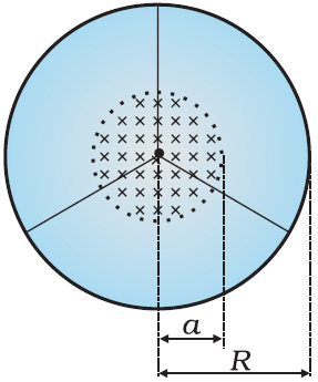
Questions

3 Marks Question

Take a timed test

37 questions · self-marked practice — reveal the answer and mark yourself.

Question 13 Marks
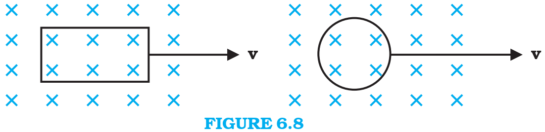
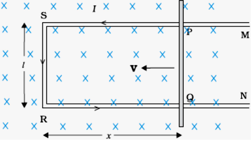
A rectangular wire loop of sides $8\ cm$ and $2\ cm$ with a small cut is moving out of a region of uniform magnetic field of magnitude $0.3T$ directed normal to the loop. What is the emf developed across the cut if the velocity of the loop is $1 \ cms^{–1}$ in a direction normal to the:
  1. Longer side,
  2. shorter side of the loop?
For how long does the induced voltage last in each case?
Answer
Length of the rectangular wire, $l = 8\ cm = 0.08m$ Width of the rectangular wire, $b = 2\ cm = 0.02m$ Hence, area of the rectangular loop, $A = lb = 0.08 \times 0.02 = 16 \times 10^{-4}m^2$ Magnetic field strenght, $B = 0.3T$ Velocity of the loop, $v = 1\ cm/s = 0.001m/s$
  1. Emf developed in the loop is given as:
$e = \text{BIV}$
$= 0.3 \times 0.08 \times 0.01 = 2.4 \times 10^{-4}V$
Time taken to travel along the width,
$\text{t}=\frac{\text{Distance travelled}}{\text{Velocity}}=\frac{\text{b}}{\text{v}}$
$=\frac{0.02}{0.01}=2\text{s}$
Hence, the induced voltage is $2.4\ x\ 10^{-4}V$ which lasts for $2s.$
  1. Emf developed, e $= Bbv$
$= 0.3 \times 0.02 \times 0.01 = 0.6 \times 10^{-4}V$
Time taken to travel along the length,
$\text{t}=\frac{\text{Distance travelled}}{\text{Velocity}}=\frac{\text{l}}{\text{v}}$
$=\frac{0.08}{0.01}=8\text{s}$
Hence, the induced voltage is $0.6\ x\ 10^{-4}V$ which lasts for $8s.$
View full question & answer
Question 23 Marks
A line charge $\lambda$ per unit length is lodged uniformly onto the rim of a wheel of mass $M$ and radius $R.$ The wheel has light non-conducting spokes and is free to rotate without friction about its axis $($Fig.$). A$ uniform magnetic field extends over a circular region within the rim. It is given by,
$B = – B_0k (r \leq a; a < R)$
$= 0 ($otherwise$)$
What is the angular velocity of the wheel after the field is suddenly switched off?
Answer
Line charge per unit length $=\lambda=\frac{\text{Total charge}}{\text{Length}}=\frac{\text{Q}}{2\pi\text{r}}$
Where,
$r =$ Distance of the point within the wheel
Mass of the wheel $= M$
Radius of the wheel $= R$
Magnetic field, $\text{B}=-\overrightarrow{\text{B}}=\text{B}_0{^{\triangle}_{\ \text{k}}}$
At distance $r,$ the magnetic force is balanced by the centripetal force i.e.,
$\text{BQv}=\frac{\text{M}\text{v}^2}{\text{r}}$
Where
$V =$ linear velocity of the wheel
$\therefore\ \text{B}2\pi\text{r}\lambda\text{r}^2=\frac{\text{Mv}}{\text{r}}$
$\text{v}=\frac{\text{B}2\pi\text{r}\lambda\text{r}^2}{\text{M}}$
$\text{BQv}=\frac{\text{M}\text{v}^2}{\text{r}}$
For $\text{r}\leq\text{a}$ and $\ \text{a}<\text{R} , $we get :
$(\text{i})=-\frac{2\text{B}_0\text{a}^2\lambda}{\text{MR}}\text{k}$
View full question & answer
Question 33 Marks
An air $-$ cored solenoid with length $30\ cm,$ area of cross $-$ section $25\ cm^2$ and number of turns $500,$ carries a current of $2.5A$. The current is suddenly switched off in a brief time of $10^{–3}s$. How much is the average back emf induced across the ends of the open switch in the circuit? Ignore the variation in magnetic field near the ends of the solenoid.
Answer
Length of the solenoid $, l = 30\ cm = 0.3m$
Area of cross-section $, A = 25\ cm^2 = 25 \times 10^{-4}m^2$
Number of turns on the solenoid $, N = 500$
Current in the solenoid $, I = 2.5A$
Current flows for time $, t = 10^{-3}s$
Average back emf, $\text{e}=\frac{\text{d}\phi}{\text{dt}}\ \ ....(1)$
Where,
$\text{d}\phi=$ Charge in flux
$= \text{ NAB} ...(2)$
Where,
$B =$ Magnetic field strength
$=\mu_0\frac{\text{Nl}}{\text{l}}\ \ \ ......(3)$
Where,
$\mu_0=$ Permeability of free space $= 4\pi\times 10^{-7}\text{TmA}^{-1}$
Using equations $(2)$ and $(3)$ in equation $(1),$ we get
$\text{e}=\frac{\mu_0\text{N}^2\text{lA}}{\text{lt}}$
$=\frac{4\pi\times10^{-7}\times(500)^2\times2.5\times25\times10^{-4}}{0.3\times10^{-3}}=6.5\text{V}$
Hence, the average back emf induced in the solenoid is $6.5V$.
View full question & answer
Question 43 Marks
A circular coil of radius $8.0\ cm$ and $20$ turns is rotated about its vertical diameter with an angular speed of $50$ rad $s^{–1}$ in a uniform horizontal magnetic field of magnitude $3.0 \times 10^{–2}T$. Obtain the maximum and average emf induced in the coil. If the coil forms a closed loop of resistance $10\Omega ,$ calculate the maximum value of current in the coil. Calculate the average power loss due to Joule heating. Where does this power come from?
Answer
Max induced emf $= 0.603V$
Average induced emf $= 0V$
Max current in the coil $= 0.0603A$
Average power loss $= 0.018W$
$($Power comes from the external rotor$)$
Radius of the circular coil $, r = 8\ cm = 0.08m$
Area of the coil, $\text{A}=\pi\text{r}^2=\pi\times(0.08)^2\text{m}^2$
Number of turns on the coil $, N = 20$
Angular speed, $\omega=50\text{ rad/s}$
Magnetic field strength $, B = 3 x 10^{-2}T$
Resistance of the loop, $\text{R}=10\Omega$
Maximum induced emf is given as:
$e=\text{N}\omega\text{AB}$
$=20\times50\times\pi\times(0.08)^2\times3\times10^{-2}$
$= 0.603V$
The maximum emf induced in the coil is $0.603V.$
Over a full cycle, the average emf induced in the coil is zero.
Maximum current is given as:
$\text{I}=\frac{\text{e}}{\text{R}}$
$=\frac{0.603}{10}=0.0603\text{ A}$
Average power loss due to joule heating:
$\text{P}=\frac{\text{eI}}{2}$
$=\frac{0.603\times0.0603}{2}=0.018\text{ mW}$
The current induced in the coil produces a torque opposing the rotation of the coil.
The rotor is an external agent. It must supply a torque to counter this torque in order to keep the coil rotating uniformly.
Hence, dissipated power comes from the external rotor.
View full question & answer
Question 53 Marks
A jet plane is travelling towards west at a speed of $1800\ km/h.$ What is the voltage difference developed between the ends of the wing having a span of $25m,$ if the Earth’s magnetic field at the location has a magnitude of $5 \times 10^{–4}T$ and the dip angle is $30^\circ .$
Answer
Speed of the jet plane, $v = 1800\ km/h = 500\ m/s$
Wing spanof jet plane, $I = 25m$
Earth's magnetic field strength, $B = 5.0 \times 10^{-4}T$
Angle of dip, $\delta=30^{\circ}$
Vertical component of Earth's magnetic field,
$\text{B}_{\text{v}}=\text{B}\sin\delta$
$=5\times10^{-4}\sin30^{\circ}$
$= 2.5 \times 10^{-4}T$
Voltage difference between the ends of the wing can be calculated as:
$e = (B_v) \times I \times v$
$= 2.5 \times 10^{-4} \times 25 \times 500$
$= 3.125V$
Hence, the voltage difference developed between the ends of the wings is
$3.125 v.$
View full question & answer
Question 63 Marks
A pair of adjacent coils has a mutual inductance of $1.5H.$ If the current in one coil changes from $0$ to $20A$ in $0.5s,$ what is the change of flux linkage with the other coil?
Answer
Mutual inductance of a pair of coils, $\mu=1.5\text{ H}$
Initial current, $I_1 = 0A$
Final current $I_2 = 20A$
Change in current, $dI = I_2 - I_1 = 20 - 0 = 20A$
Time taken for the change, $t = 0.5s$
Induced emf, $\text{e}=\frac{\text{d}\phi}{\text{dt}}\ \ \ ...(1)$
where $\text{d}\phi$ is the change in the flux linkage with the coil.
Emf is related with mutual inductance as:
$\text{e}=\mu\frac{\text{dI}}{\text{dt}}\ \ \ ...(2)$
Equating equations $(1)$ and $(2),$ we get
$\frac{\text{d}\phi}{\text{dt}}=\mu\frac{\text{dI}}{\text{dt}}$
$\text{d}\phi=1.5\times(20)$
$= 30Wb$
Hence, the change in the flux linkage is $30Wb.$
View full question & answer
Question 73 Marks
A horizontal straight wire $10m$ long extending from east to west is falling with a speed of $5.0\ ms^{–1},$ at right angles to the horizontal component of the earth’s magnetic field, $0.30 \times 10^{–4}Wbm^{–2}.$
  1. What is the instantaneous value of the emf induced in the wire?
  2. What is the direction of the emf?
  3. Which end of the wire is at the higher electrical potential?
​​​​​​​
Answer
  1. Emf induced in the wire,
  1. $e = Blv$
  2. $= 0.3 \times 10^{-4} \times 5 \times 10$
    $= 1.5 \times 10^{-3}V$
  3. Using Fleming's right hand rule, it can be inferred that the direction of the induced emf is from West to East.
  4. The eastern end of the wire is at a higher potential.
View full question & answer
Question 83 Marks
$(a)$ Obtain the expression for the magnetic energy stored in a solenoid in terms of magnetic field $B,$ area $A$ and length $l$ of the solenoid. $(b)$ How does this magnetic energy compare with the electrostatic energy stored in a capacitor?
Answer
$(a)$ From Eq. $(6.17),$ the magnetic energy is
$U_B =\frac{1}{2} L I^2$
$ =\frac{1}{2} L\left(\frac{B}{\mu_0 n}\right)^2$
Since  $B=\mu_0 n I,.$ for a solenoid 
$=\frac{1}{2}\left(\mu_0 n^2 A l\right)\left(\frac{B}{\mu_0 n}\right)^2 \ [$from Eq. $(6.15)]$
$=\frac{1}{2 \mu_0} B^2 A l$
$(b)$ The magnetic energy per unit volume is,
$u_B =\frac{U_B}{V} \ ($where $V $ is volume that contains flux$)$
$ =\frac{U_B}{A l}$
$ =\frac{B^2}{2 \mu_0}$
We have already obtained the relation for the electrostatic energy stored per unit volume in a parallel plate capacitor $($refer to Chapter $2,$ Eq. $2.73),$
$u_E=\frac{1}{2} \varepsilon_0 E^2$
In both the cases energy is proportional to the square of the field strength.
Equations $(6.18)$ and $(2.73)$ have been derived for special cases: a solenoid and a parallel plate capacitor, respectively.
But they are general and valid for any region of space in which a magnetic field or/and an electric field exist.
View full question & answer
Question 93 Marks
Two concentric circular coils, one of small radius $r_1$ and the other of large radius $r_2$, such that $r_1 \ll r_2$, are placed co-axially with centres coinciding. Obtain the mutual inductance of the arrangement.
Answer
Let a current $I_2$ flow through the outer circular coil. The field at the centre of the coil is $B_2=\mu_0 I_2 / 2 r_2$. Since the other co-axially placed coil has a very small radius, $B_2$ may be considered constant over its cross-sectional area. Hence,
$
\begin{aligned}
\Phi_1 & =\pi r_1^2 B_2 \\
& =\frac{\mu_0 \pi r_1^2}{2 r_2} I_2 \\
& =M_{12} I_2
\end{aligned}
$
Thus,
$
M_{12}=\frac{\mu_0 \pi r_1^2}{2 r_2}
$
From Eq. (6.12)
$
M_{12}=M_{21}=\frac{\mu_0 \pi r_1^2}{2 r_2}
$
Note that we calculated $M_{12}$ from an approximate value of $\Phi_1$, assuming the magnetic field $B_2$ to be uniform over the area $\pi r_1^2$. However, we can accept this value because $r_1 \ll r_2$.
View full question & answer
Question 103 Marks
A metallic rod of $1 m$ length is rotated with a frequency of $50 \text
{ rev / s}$, with one end hinged at the centre and the other end at the circumference of a circular metallic ring of radius $1 m$, about an axis passing through the centre and perpendicular to the plane of the ring $($Fig.$ 6.11)$. A constant and uniform magnetic field of $1 T$ parallel to the axis is present everywhere. What is the emf between the centre and the metallic ring?
Image ​​​​​​​
Answer
Method $I$
As the rod is rotated, free electrons in the rod move towards the outer end due to Lorentz force and get distributed over the ring.
Thus, the resulting separation of charges produces an emf across the ends of the rod. At a certain value of emf, there is no more flow of electrons and a steady state is reached.
Using Eq. $(6.5),$ the magnitude of the emf generated across a length $d r$ of the rod as it moves at right angles to the magnetic field is given by
$d \varepsilon=\text{B vdr}$. Hence,
$\varepsilon f d \varepsilon=\int_\text{0^R B v d r}=\int_0^R B \omega\ \text{r d r} =\frac{B \omega R^2}{2}$
Note that we have used $v=\omega r$. This gives
$\varepsilon=\frac{1}{2} \times 1.0 \times 2 \pi \times 50 \times\left(1^2\right)$
$=157 V$
Method $II$
To calculate the emf, we can imagine a closed loop $\text{OPQ}$ in which point $O$ and $P$ are connected with a resistor $R$ and $OQ$ is the rotating rod.
The potential difference across the resistor is then equal to the induced emf and equals $B \times ($rate of change of area of loop$)$. I
f $\theta$ is the angle between the rod and the radius of the circle at $P$ at time $t$, the area of the sector $\text{OPQ}$ is given by $ \pi R^2 \times \frac{\theta}{2 \pi}=\frac{1}{2} R^2 \theta $ where $R$ is the radius of the circle.
Hence, the induced emf is $ \varepsilon=B \times \frac{ d }{ d t}\left[\frac{1}{2} R^2 \theta\right]$
$=\frac{1}{2} B R^2 \frac{ d \theta}{ d t}=\frac{B \omega R^2}{2} $
$ [$Note: $\frac{ d \theta}{ d t}=\omega=2 \pi v ]$
This expression is identical to the expression obtained by Method I and we get the same value of $\varepsilon$.
View full question & answer
Question 113 Marks
(a) A closed loop is held stationary in the magnetic field between the north and south poles of two permanent magnets held fixed. Can we hope to generate current in the loop by using very strong magnets?
(b) A closed loop moves normal to the constant electric field between the plates of a large capacitor. Is a current induced in the loop (i) when it is wholly inside the region between the capacitor plates (ii) when it is partially outside the plates of the capacitor? The electric field is normal to the plane of the loop.
(c) A rectangular loop and a circular loop are moving out of a uniform magnetic field region (Fig. 6.8) to a field-free region with a constant velocity $v$. In which loop do you expect the induced emf to be constant during the passage out of the field region? The field is normal to the loops.
Image
(d) Predict the polarity of the capacitor in the situation described by Fig. 6.9.

Image
Answer
(a) No. However strong the magnet may be, current can be induced only by changing the magnetic flux through the loop.
(b) No current is induced in either case. Current can not be induced by changing the electric flux.
(c) The induced emf is expected to be constant only in the case of the rectangular loop. In the case of circular loop, the rate of change of area of the loop during its passage out of the field region is not constant, hence induced emf will vary accordingly.
(d) The polarity of plate ' $A$ ' will be positive with respect to plate ' $B$ ' in the capacitor.
View full question & answer
Question 123 Marks
shows planar loops of different shapes moving out of or into a region of a magnetic field which is directed normal to the plane of the loop away from the reader. Determine the direction of induced current in each loop using Lenz's law.
Image
Answer
(i) The magnetic flux through the rectangular loop abcd increases, due to the motion of the loop into the region of magnetic field, The induced current must flow along the path bcdab so that it opposes the increasing flux.
(ii) Due to the outward motion, magnetic flux through the triangular loop abc decreases due to which the induced current flows along bacb, so as to oppose the change in flux.
(iii) As the magnetic flux decreases due to motion of the irregular shaped loop abcd out of the region of magnetic field, the induced current flows along cdabc, so as to oppose change in flux. Note that there are no induced current as long as the loops are completely inside or outside the region of the magnetic field.
View full question & answer
Question 133 Marks
A circular coil of radius $10 cm , 500$ turns and resistance $2 \Omega$ is placed with its plane perpendicular to the horizontal component of the earth's magnetic field. It is rotated about its vertical diameter through $180^{\circ}$ in $0.25 s$. Estimate the magnitudes of the emf and current induced in the coil. Horizontal component of the earth's magnetic field at the place is $3.0 \times 10^{-5} T$.
Answer
Initial flux through the coil,
$
\begin{aligned}
\Phi_{ B \text { (initial) }} & =B A \cos \theta \\
& =3.0 \times 10^{-5} \times\left(\pi \times 10^{-2}\right) \times \cos 0^{\circ} \\
& =3 \pi \times 10^{-7} Wb
\end{aligned}
$

Final flux after the rotation,
$
\begin{aligned}
\Phi_{ B (\text { final) }} & =3.0 \times 10^{-5} \times\left(\pi \times 10^{-2}\right) \times \cos 180^{\circ} \\
& =-3 \pi \times 10^{-7} Wb
\end{aligned}
$

Therefore, estimated value of the induced emf is,
$
\begin{aligned}
\varepsilon & =N \frac{\Delta \Phi}{\Delta t} \\
& =500 \times\left(6 \pi \times 10^{-7}\right) / 0.25 \\
& =3.8 \times 10^{-3} V \\
I & =\varepsilon / R=1.9 \times 10^{-3} A
\end{aligned}
$
Note that the magnitudes of $\varepsilon$ and $I$ are the estimated values. Their instantaneous values are different and depend upon the speed of rotation at the particular instant.
View full question & answer
Question 143 Marks
A square loop of side $10 \ cm$ and resistance $0.5 \Omega$ is placed vertically in the east $-$ west plane. $A$ uniform magnetic field of $0.10 T$ is set up across the plane in the north-east direction. The magnetic field is decreased to zero in $0.70 s$ at a steady rate. Determine the magnitudes of induced emf and current during this time $-$ interval.
Answer
The angle $\theta$ made by the area vector of the coil with the magnetic field is $45^{\circ}$.
From Eq. $(6.1),$ the initial magnetic flux is
$\Phi=B A \cos \theta$
$=\frac{0.1 \times 10^{-2}}{\sqrt{2}} Wb$
Final flux, $\Phi_{\min }=0$
The change in flux is brought about in $0.70 s$.
From Eq. $(6.3),$ the magnitude of the induced emf is given by
$\varepsilon=\frac{\left|\Delta \Phi_B\right|}{\Delta t}=\frac{|(\Phi-0)|}{\Delta t}=\frac{10^{-3}}{\sqrt{2} \times 0.7}=1.0 mV$
And the magnitude of the current is
$I=\frac{\varepsilon}{R}=\frac{10^{-3} V }{0.5 \Omega}=2 mA$
Note that the earth's magnetic field also produces a flux through the loop.
But it is a steady field $($which does not change within the time span of the experiment$)$ and hence does not induce any $\text {emf}.$
View full question & answer
Question 153 Marks
  1. A rod of length l is moved horizontally with a uniform velocity ‘v’ in a direction perpendicular to its length through a region in which a uniform magnetic field is acting vertically downward. Derive the expression for the emf induced across the ends of the rod.
  2. How does one understand this motional emf by invoking the Lorentz force acting on the free charge carriers of the conductor? Explain.
Answer

  1. Imagine the rod PQ to be moving with a velocity v from its initial (varying) position towards some position SR.
The magnetic flux, enclosed by the loop PQRS, at the instant.
shown,is
$\phi=Blx$
$\therefore{e}=-\frac{d\phi}{dt}=-Bl\frac{dx}{dt}$
$=Blv\ \ \ \ \ \ \ \ \ \ \ \ \ (\therefore{v}=-\frac{dx}{dt})$
  1. Lorentz force, on a charge q, moving with a speed v, in a (normal) uniform magnetic field B, is Bqv.
All charges experience the same force. Work done to move the charge from P to Q, is
$W = {\text{Bq}}v× l$
$\therefore{e}=\frac{W}{q}=\frac{Bqvl}{q}=Blv$
View full question & answer
Question 163 Marks
Define the term ‘mutual inductance’ between the two coils.
Obtain the expression for mutual inductance of a pair of long coaxial solenoids each of length $l$ and radii $r_1$ and $r_2 (r_2 >> r_1).$ Total number of turns in the two solenoids are $N_1$ and $N_2$ respectively.
Answer
Mutual inductance, between a pair of coils, equals the magnetic flux, linked with one of them, due to a unit current flowing in the other.Alternate Answer
The mutual inductance, for a pair of coils, equals the emf induced, in one of them, when the current in the

Let a current $I_2$ flow through the outer coil. The magnetic field due to this current $ = \mu_{o}\frac{\text{N}_{2}}{l}\times\text{I}_{2}$ The resulting magnetic flux linked with the inner coil $ = \phi_{12} = \text{N}_{1}.\big(\mu_{o}\frac{\text{N}_{2}}{l}\times\text{I}_{2}\big)\times\pi\text{r}_{1}^{2}$
$ = \bigg(\mu_{o}\frac{\text{N}_{1}\text{N}_{2}}{l}.\pi\text{r}^{2}_{1}\bigg)\text{I}_{2} = M_{12} I_2$
$\therefore\text{M}_{12} = \mu_{o}\frac{\text{N}_{1}\text{N}_{2}}{l}.\pi\text{r}^{2}_{1}.$
View full question & answer
Question 173 Marks
  1. State Faraday’s law of electromagnetic induction.
  2. A jet plane is travelling towards west at a speed of $1800 \ km/h$. What is the voltage difference developed between the ends of the wing having a span of $25 m,$ if the Earth’s magnetic field at the location has a magnitude of $5 x 10^{–4} T$ and the dip angle is $30^\circ$ ?
Answer
  1. Faraday’s law of electromagnetic induction: The magnitude of the induced emf in a circuit is equal to the rate of change of magnetic flux with time through the circuit.
Alternate Answer
$\varepsilon = -\frac{\text{d}\Phi_{B}}{\text{dt}}$
  1. We have:
$\text{B}_{v} = \text{B}\sin\theta$
Also, Induced emf $ = \varepsilon = \text{B}_{v}.\text{v}\ell$
$\therefore\varepsilon =5\times10^{-4}.(\sin30^{0})\times\frac{1800\times10^{3}}{3600}\times25\text{V}$
$ = 3.125\text{V}.$
View full question & answer
Question 183 Marks
What are eddy currents? How are these produced? In what sense are eddy currents considered undesirable in a transformer and how are these reduced in such a device?
Answer
Eddy current: When magnetic flux linked with a metallic sheet changes, the induced current produced in it, are known as eddy currents.
Production: Production due to flux changes, a current is induced in the plate which seeks a path of least resistance and there by flows along irregularly shaped loops.
Undesirable–Due to heating effect.
Reduction–Laminated core.
View full question & answer
Question 193 Marks
  1. Define self $-$ inductance. Write its $SI$ units.
  2. A long solenoid with $15$ turns per $\ cm$ has a small loop of area $2.0 \ cm^2$ placed inside the solenoid normal to its axis. If the current carried by the solenoid changes steadily from $ 2.0 A$ to $4.0 A$ in $0.1 s,$ what is the induced emf in the loop while the current is changing?
Answer
  1. Self $-$ inductance is the amount of magnetic flux linked with a coil when a unit current flows through it.
$($Alternatively, It is the amount of emf induced in a coil when current through it changes at the rate of $1 A$ per second.$)$
$S.I.$ Unit: henry $(H)$
  1. Magnetic field inside the solenoid $, B=\mu_0\text{n I}$
Induced emf in the loop, $\epsilon=\frac{d\phi_B}{dt}$
$=A\frac{dB}{Dt}$
$=\mu_0nA\frac{dI}{dt}$
$=4\pi\times10^{-7}\times1500\times2\times10^{-4}\times\frac{(4-2)}{0.1}\text{V}$
$=7.5\times10^{-6}\text{V}$
View full question & answer
Question 203 Marks
  1. Define mutual inductance.
  2. A pair of adjacent coils has a mutual inductance of 1.5 H. If the current in one coil changes from 0 to 20 A in 0.5 s, what is the change of flux linkage with the other coil?
Answer
Magnetic flux, linked with the secondary coil due to the unit current flowing in the primary coil, $\phi_{2} = \text{MI}_{1}$Alternate Answer
Induced emf associated with the secondary coil, for a unit rate of change of current in the primary coil. $\text{e}_{2} = - \text{M}\frac{\text{dl}_{1}}{\text{dt}} ] $ [i.e. the phenomenon of production of induced emf in one coil due to change in current in neighbouring coil ] Change of flux linkage - $\text{d}\phi = \text{M}\text{dI}$ $ = 1.5\times(20 - 0 )\text{W}$ $ = 30\text{weber}$.
View full question & answer
Question 213 Marks
A metallic rod of length ‘l’ is rotated with a frequency v with one end hinged at the centre and the other end at the circumference of a circular metallic ring of radius r, about an axis passing through the centre and perpendicular to the plane of the rinig. A constant uniform magnetic field B parallel to the axis is present every where. Using Lorentz force, explain how emf is induced between the centre and the metallic ring and hence obtain the expression for it.
Answer
As the rod is rotated, free electrons in the rod move towards the outer end due to Lorentz force and get distributed over the ring. Thus, the resulting separation of charges produces an emf across the ends of the rod. At a certain value of emf, there is no more flow of electrons and a steady state is reached.
Expression for Induced emf in a Rotating Rod.
Consider a metallic rod OA of length l , which is rotating with angular velocity $\omega$ in a uniform magnetic field B , the plane of rotation being perpendicular to the magnetic field. A rod may be supposed to be formed of a large number of small elements. Consider a small element of length dx at a distance x from centre.
If v is the linear velocity of this element, then area swept by the element per second =v dx.

The emf induced across the ends of element
$\text{d}\varepsilon = \text{B}\frac{\text{dA}}{\text{dt}} =\text{B} vdx$
$\text{But} v = x\omega$
$\therefore\text{d}\varepsilon = \text{B}x\omega\text{dx}$
$\therefore$ The emf induced across the rod
$\varepsilon = \int_{0}^{l}\text{B}\text{x}\omega\text{dx} = \text{B}\omega\int_{0}^{l}\text{x}\text{dx}$
$ =\text{B}\omega\bigg[\frac{\text{x}^{2}}{2}\bigg]^{l}_{0} = \text{B}\omega\bigg[\frac{l^{2}}{2} - 0\bigg] = \frac{1}{2}\text{B}\omega l^{2}$
Current induced in rod $\text{I} = \frac{\varepsilon}{\text{R}} = \frac{1}{2}\frac{\text{B}\omega l^{2}}{\text{R}}$
It circuit is closed, power dissipated,
$ = \frac{\varepsilon^{2}}{\text{R}} = \frac{\text{B}^{2}\omega^{2}l^{2}}{4\text{R}}.$
View full question & answer
Question 223 Marks
  1. Define self inductance. Write its $S.I. $units.
  2. Derive an expression for self inductance of a long, solenoid of length $l, $cross sectional area $A$ having $N$ number of turns.
Answer
Self inductance: is defined as the magnetic flux passing through the coil when a unit current flows through it.Alternate Answer
It is the emf induced in the coil when the rate of change of current through it is unity.
SI Unit is henry
The magnetic field due to a current I flowing in the solenoid is $B =µ_0nI$
The total flux linked with the solenoid is $\text{NBA}$, i.e.
$\phi =\big(\text{nl}\big)\big(\mu_\circ\text{nI}\big)\text{A}$
$ = \mu_\circ\text{n}^{2}\ \text{IlA}$
$\text{L} =\frac{\phi}{\text{I}} =\mu_\circ\text{n}^{2} \text{Al}$
$ = \frac{\mu_\circ\text{N}^{2}\text{A}}{l}$
View full question & answer
Question 233 Marks
A metallic rod of length l is rotated at a constant angular speed $\omega , $  normal to a uniform magnetic field B. Derive an expression for the current induced in the rod, if the resistance of the rod is R.
Answer
  1. Figure.
 
  1. Induced emf $\varepsilon = \int\limits_{0}^{\ell}\text{B}\omega\text{rdr}$
$= \int\limits_{0}^{\ell}\text{B}\omega\text{rdr}$
$\frac{\text{B}\omega\text{l}^{2}}{2}$
  1. Current  $ = \frac{\text{E}}{\text{R}} = \frac{\text{B}\omega\text{l}^{2}}{2\text{R}}$
Note:
  1. If the rod is assumed to rotate about an axis, passing through its mid-point, the expression for the induced emf and current will be.
$\varepsilon = \frac{\text{B}\omega\text{l}^{2}}{8\text{R}}$  and 
$\text{I}= \frac{\text{B}\omega\text{l}^{2}}{8\text{R}}$ respectively.​​​​​​​
View full question & answer
Question 243 Marks
How is the mutual inductance of a pair of coils affected when:
  1. Separation between the coils is increased?
  2. The number of turns of each coil is increased?
  3. A thin iron sheet is placed between the two coils, other factors remaining the same? Explain your answer in each case.
Answer
  1. Decreases:
Because the magnetic flux linked with the second coil decreases/coupling between them becomes weaker.
  1. Increases:
Because magnetic field produced by current-carrying coil and its flux linked with the second coil will increase.
Alternate Answer
The mutual inductance.
$\text{M}=\mu{_\circ}n{_1}n{_2}\text{A}1\Rightarrow\text{M is proportional to n}{_1}\text{n}_{2}$
  1. Increases:
Because magnetic permeability increases.
$\text{& M} \alpha \mu.$
View full question & answer
Question 253 Marks
State the underlying principle of a cyclotron. Explain its working with the help of a schematic diagram. Obtain the expression for cyclotron frequency.
Answer
Cyclotron works on the principle that kinetic energy of the charged particle is increased when they move in crossed oscillating electric and magnetic fields again and again. 
When charged particle enter is inside the metal boxes, no electric field acts on them, the magnetic field however acts on the particle and makes it go round in a circular path inside the metal boxes, (dees), everytime when particle moves one dee to another it is acted upon by the electric field and the sign of electric field changes alternatively in turn with the circular motion of the particle, hence particle is accelerated, which in turn increases the kinetic energy of it. $\frac{\text{mv}^2}{\text{r}}=\text{qvB}$ $\text{r}=\frac{\text{mv}}{\text{qB}}$ frequency $\text{V}=\frac{\text{v}}{2\pi\text{r}}=\frac{\text{v}}{2\pi\Big(\frac{\text{mv}}{\text{qB}}\Big)}=\frac{\text{qB}}{2\pi\text{m}}$
View full question & answer
Question 263 Marks
  1. Define mutual inductance and write its $S.I$. unit.
  2. A square loop of side $'a\ '$carrying a current $I_2$ is kept at distance $x$ from an infinitely long straight wire carrying a current $ I_1$ as shown in the figure. Obtain the expression for the resultant force acting on the loop.
Answer
  1. Mutual inductance is where the magnetic field generated by a coil of wire induces voltage in an adjacent coil of wire. $A$ transformer is a device constructed of two or more coils in close proximity to each other, with the express purpose of creating a condition of mutual inductance between the coils. It's $SI$ unit is: $\frac{\text{Wb}}{\text{A}}$
  2.  

According to the right $-$ hand screw rule, the magnetic field will be into the plane across the loop.
Force on length $AD$ :
$F =$ Bil
$\text{F}_1=\frac{\mu_0\text{I}_1\text{I}_2\text{a}}{2\pi\text{x}} \ ($Towards Right$)$
Force on length $AD$ :
$F =$ Bil
$\text{F}_2=\frac{\mu_0\text{I}_1\text{I}_2\text{a}}{2\pi(\text{x}+\text{a})} \ ($Towards Left$)$
Force on $AB$ and $CD$ will be equal and opposite.
Hence, they'll cancel out.
Force on the loop:
$\text{F}_\text{Net}=\text{F}_1-\text{F}_2$
$=\frac{\mu_0\text{I}_1\text{I}_2\text{a}}{2\pi}\Big[\frac{1}{\text{x}}-\frac{1}{(\text{x}+\text{a})}\Big]$
$\text{F}_\text{Net}=\frac{\mu_0\text{I}_1\text{I}_2\text{a}}{2\pi}\Big[\frac{\text{x}+\text{a}-\text{x}}{(\text{x}+\text{a})\text{x}}\Big]=\frac{\mu_0\text{I}_1\text{I}_2\text{a}^2}{2\pi(\text{x}+\text{a})\text{x}}$
$\text{F}_\text{Net}=\frac{\mu_0\text{I}_1\text{I}_2\text{a}^2}{2\pi\text{x}(\text{x}+\text{a})}  \ ($Towards left$)$
View full question & answer
Question 273 Marks

In the figure given below, a bar magnet moving towards the right or left induces an emf in the coils (1) and (2). Find, giving reason, the directions of the induced currents through the resistors AB and CD when the magnet is moving (a) towards the right, and (b) towards the left.
Answer
  1. When magnet moves towards the right, the nearer faces of coils, 1 and 2 act as south poles, so current induced in AB is from B to A and in coil 2 from C to D.
  2. When magnet moves towards left, the nearer faces of coils act as north poles, so current induced in coil, 1 will be from A to B and in coil 2 from D to C.
View full question & answer
Question 283 Marks

Predict the direction of induced current in the situations described in the following figs.
Answer
  1. When the tapping key is just closed, the current produced in the left loop flows clockwise, so magnetic field induced will flow along negative axis; the current induced in right coil will oppose the magnetic field produced, so current in right coil will flow anticlockwise, i.e., direction of current will be along yzx.
  2. The current in coil is anticlockwise. When rheostat setting is being changed, the resistance of the right circuit is decreasing, so current is increasing, the current induced in left loop will oppose the increase of current, so current induced in left coil will flow clockwise i.e., along zyx.
  3. Induced current in the right coil is along xry.
  4. No induced current because magnetic field lines lie in the plane of loop.
View full question & answer
Question 293 Marks

Predict the direction of induced current in the situations described in the following figs.
Answer
  1. The direction of current is along qrpq because the current induced in solenoid will oppose the approach of magnet, so from looking on magnet side, the current at nearer face should flow clockwise.
  2. In this case the current induced in coil pq will oppose the approach of magnet while coil xy will oppose the recession of magnet; so nearer faces of coils will act as S-poles. Accordingly the direction of current in coil pq will be along qrp and in coil xy it will be along yzx.
View full question & answer
Question 303 Marks

A cylindrical bar magnet is kept along the axis of a circular coil and near it as shown in figure. Will there be any induced emf at the terminals of the coil, when the magnet is rotated:
  1. About its own axis.
  2. About an axis perpendicular to the length of the magnet?
Answer
  1. When the magnet is rotated about its own axis, then due to symmetry of magnet the magnetic flux linked with circular coil remains unchanged, hence no emf is induced at terminals of coil.
  2. When the magnet is rotated about an axis perpendicular to the length, the positions of N and S poles of magnet changes continuously, so the magnetic flux linked with the coil changes continuously, hence the emf is induced at the terminals of the coil.
View full question & answer
Question 313 Marks
The given graph shows a plot of magnetic flux $(\phi)$ and the electric current (I) flowing through two inductors P and Q. Which of the two inductors has smaller value of self-inductance?
Answer
Inductor:
$\text{P},\phi=\text{LI}\Rightarrow\text{L}=\frac{\phi}{\text{I}}$
For $\text{P},\frac{\phi}{\text{I}}$ is lesser so, it has smaller value of self inductance.
View full question & answer
Question 323 Marks
Two circular loops are placed coaxially but separated by a distance. A battery is suddenly connected to one of the loops establishing a current in it. Will there be a current induced in the other loop? If yes, when does the current start and when does it end? Do the loops attract each other or do they repel?
Answer
When there is some current in first loop it will induce same polarity current in the second loop. It starts when the current is passed through first loop and ends when the current is stopped.
Loops repel each other as loops have current in same direction thus they have same pole as magnet.
View full question & answer
Question 333 Marks
Fig. shows two positions of a loop PQR in a perpendicular uniform magnetic field. In which position of the coil is there an induced emf?
Answer
In position:
  1. The coil remains as such in magnetic field, so there is no magnetic flux change in the coil, hence no emf is induced.
In position:
  1. The coil is coming out of the magnetic field, so the magnetic flux linked with it decreases and so an emf is induced in the coil.
View full question & answer
Question 343 Marks
A short magnet is moved along the axis of a conducting loop. Show that the loop repels the magnet if the magnet is approaching the loop and attracts the magnet if it is going away from the loop.
Answer
Due to movement of magnet the current is induced inside loop and thus when magnet is pushed into loops the current is increased and it starts repelling the magnet. When magnet is taken away from the loop the current starts decreasing and thus acts in opposite direction so as to attract the magnet.
View full question & answer
Question 353 Marks

A rectangular wire frame, shown below, is placed in a uniform magnetic field directed upward and normal to the plane of the paper. The part AB is connected to a spring. The spring is stretched and released when the wire AB has come to the position A′ B′ (t = 0) How would the induced emf vary with time? Neglect damping.
Answer
When the spring is stretched and released, the wire AB will execute simple harmonic (sinusoidal) motion, so induced emf will vary periodically. At t = 0, wire is at the extreme position. $\text{v}=0.$ $\text{v}=\text{A}\omega\sin\omega\text{t}$ Induced emf $\varepsilon = \text{Bvl}$ $=\text{BA}\omega\text{l}\sin\omega\text{t}$ Where A = BB′= AA′ is the amplitude of motion and ω is angular frequency.
View full question & answer
Question 363 Marks
A bar magnet M is dropped so that it falls vertically through the coil C. The graph obtained for voltage produced across the coil versus time is showing in figure (b).
  1. Explain the shape of the graph.
  2. Why is the negative peak longer than the positive peak?
Answer
  1. When the bar magnet falls through the coil, the magnetic flux linked with the coil changes, so an emf (or pd) is developed across the coil.
Initially, the rate of increase of flux increases, becomes maximum and then it decreases, becomes zero. Now, magnetic flux begins to decrease, the rate of decrease increases becomes maximum and then it decreases and when the magnet is sufficiently far on the other side, the flux becomes zero and so pd induced becomes zero.
  1. Negative peak is longer than Positive peak because magnet moves out of coil faster than it moves into the coil, so the rate of decrease of magnetic flux is faster than the rate of increase of flux.
View full question & answer
Question 373 Marks
A $0.5m$ long metal rod $PQ$ completes the circuit as shown in the figure. The area of the circuit is perpendicular to the magnetic field of flux density $0.15T.$ If the resistance of the total circuit is $3\Omega$ calculate the force needed to move the rod in the direction as indicated with a constant speed of $2\ ms^{-1}.$
Answer
Given: $\text{l} = 0.5\text{m}, \text{B} = 0.15\text{T}, \text{R} = \Omega, \text{v} = 2\text{ms}^{-1}$

$\text{emf}.,\varepsilon=\text{vBl}$
Current, $\text{I}=\frac{\varepsilon}{\text{R}}\Rightarrow\frac{\text{vBl}}{\text{R}}$
Force needed to move the rod,
$\text{F}=\text{BIl}=\text{B}\times\frac{\text{vBl}}{\text{R}}\times\text{l}=\frac{\text{vB}^2\text{l}^2}{\text{R}}$
$=\frac{2\times(0.15)^2\times(0.5)^2}{3}=3.75\times10^{-3}\text{N}$
View full question & answer