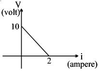
$A$ battery of $\mathrm{emf}$ $E$ and internal resistance $r$ is connected across a resistance $R$. Resistance $R$ can be adjusted to any value greater than or equal to zero. Agraph is plotted between the current $(i)$ passing through the resistance and potential difference $(V) $ across it. Select the correct alternative $(s)$.
Medium


Download our appand get started for free
Experience the future of education. Simply download our apps or reach out to us for more information. Let's shape the future of learning together!No signup needed.*
Similar Questions
- 1A resistor develops $500\, J$ of thermal energy in $20 \,s$ when a current of $1.5\, A$ is passed through it. If the current is increased from $1.5 \,A$ to $3\, A$ what will be the energy (in $J$) developed in $20\, s$.View Solution
- 2Consider four conducting materials copper, tungsten, mercury and aluminium with resistivity $\rho_{ C }, \rho_{ T }, \rho_{ M }$ and $\rho_{ A }$ espectively Then:View Solution
- 3Which of the following graph represents the variation of resistivity ( $\rho$ ) with temperature $(T)$ for copper $?$View Solution
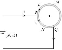
- 4A wire of resistance $10$ $\Omega$ is bent to form a circle. $P$ and $Q$ are points on the circumference of the circle dividing it into a quadrant and are connected to a Battery of $3\, V$ and internal resistance $1$ $\Omega$ as shown in the figure. The currents in the two parts of the circle areView Solution
- 5View SolutionFor which of the following the resistance decreases on increasing the temperature
- 6The temperature coefficient of resistance for a wire is $0.00125\,^oC$. At $300\,K$ its resistance is $1\, ohm$. The temperature at which the resistance becomes $2\, ohm$ is .......... $K$View Solution
- 7$A$ uniform copper wire carries a current $i$ amperes and has $p$ carriers per meter$^3$. The length of the wire is $\lambda$ meters and its cross-section area is $s$ meter $^2$. If the charge on a carrier is $q$ coulombs, the drift velocity in $ms^{-1}$ is given byView Solution
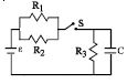
- 8The circuit shown in the figure consists of a battery of $emf$ $\varepsilon = 10 \,V$ ; a capacitor of capacitance $C = 1.0$ $ \mu F$ and three resistor of values $R_1 = 2$ $\Omega$ , $R_2 = 2$ $\Omega$ and $R_3 = 1$ $\Omega$ . Initially the capacitor is completely uncharged and the switch $S$ is open. The switch $S$ is closed at $t = 0.$View Solution
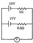
- 9A $10\,V$ battery with internal resistance $1\,\Omega $ and a $15\,V$ battery with internal resistance $0.6\,\Omega $ are connected in parallel to a voltmeter (see figure). The reading in the voltmeter will be close to ................ $V$View Solution
- 10The percentage error in the reading of the voltmeter in the figure shown here is nearly ............ $\%$View Solution