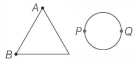
A uniform metallic wire of length $L$ is mounted in two configurations. In configuration $1$ (triangle), it is an equilateral triangle and a voltage $V$ is applied to corners $A$ and $B$. In configuration $2$ (circle), it is bent in the form of a circle and the potential $V$ is applied at diametrically opposite points $P$ and $Q$. The ratio of the power dissipated in configuration $1$ to configuration $2$ is
KVPY 2017, Advanced
Download our app for free and get started
(b)
Let $a=$ side length of equilateral triangle, $r=$ radius of circle and $x=$ resistance per unit length of wire used. Then, $L=3 a=2 \pi r$ or $a=\frac{L}{3}$ and $r=\frac{L}{2 \pi}$ Now,
Equivalent resistance across $A B$ is
$R_{A B}=(a x \| 2 a x)=\frac{a x \times 2 a x}{a x+2 a x}$
$=\frac{2 a^2 x^2}{3 a x}=\frac{2}{3} a x$
$\Rightarrow \quad R_{A B}=\frac{2}{3} \times \frac{L}{3} \times x$
Power dissipated is
$P_1=\frac{V^2}{R_{A B}}=\frac{9 V^2}{2 L x} \quad \dots(i)$
$R_{P Q}=(\pi r x \| \pi r x)=\frac{\pi r x \times \pi r x}{\pi r x+\pi r x}=\frac{\pi^2 r^2 x^2}{2 \pi r x}$
$=\frac{1}{2} \pi r x=\frac{1}{2} \pi \times \frac{L}{2 \pi} x=\frac{L x}{4}$
So, power dissipated is
$P_2=\frac{V^2}{R_{P Q}}=\frac{4 V^2}{L x}$
Ratio of power dissipated in two cases is
$\frac{P_1}{P_2}=\frac{9 V^2 / 2 L x}{4 V^2 / L x}=\frac{9}{8}$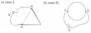

Download our appand get started for free
Experience the future of education. Simply download our apps or reach out to us for more information. Let's shape the future of learning together!No signup needed.*
Similar Questions
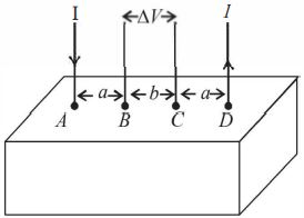
- 1Consider a block of conducting material ofresistivity '$\rho$' shown in the figure. Current '$I$' enters at '$A$' and leaves from '$D$'. We apply superp osition principle to find voltage '$\Delta V$ ' developed between '$B$' and '$C$'. The calculation is done in the following steps:View Solution
$(i)$ Take current '$I$' entering from '$A$' and assume it to spread over a hemispherical surface in the block.
$(ii)$ Calculatefield $E(r)$ at distance '$r$' from $A$ by using Ohm's law $E = \rho j$, where j is the current per unit area at '$r$'.
(iii) From the '$r$' dependence of $E(r)$, obtain the potential $V(r)$ at $r$.
(iv) Repeat $(i), (ii)$ and $(iii)$ for current '$I$' leaving '$D$' and superpose results for '$A$' and '$D$'.$\Delta V$ measured between $B$ and $C$ is
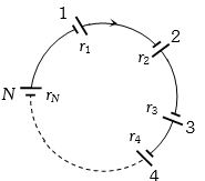
- 2A group of $N$ cells whose $emf$ varies directly with the internal resistance as per the equation $E_N = 1.5\, r_N$ are connected as shown in the figure below. The current $I$ in the circuit is ........... $amp$View Solution
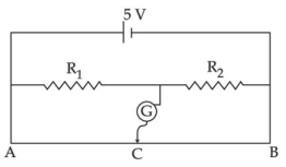
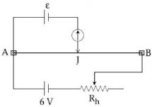
- 3The resistance of the meter bridge $AB$ in given figure is $4\,\Omega $. With a cell of emf $\varepsilon \, = 0.5\,\,V$ and rheostat resistance $R_h = 2\,\Omega $ the null point is obtained at some point $J.$ When the cell is replaced by another one of emf $\varepsilon \, = {\varepsilon _2}$ the same null point $J$ is found for $R_h = 6\,\Omega .$ The $emf$ ${\varepsilon _2}$ is ................. $V$View Solution
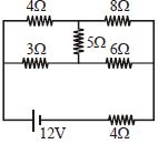
- 4In the given figure the ratio of current in $8\,\Omega $ and $3\,\Omega $ will beView Solution
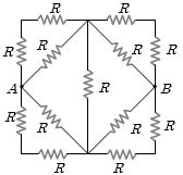
- 5Thirteen resistances each of resistance $R\, ohm$ are connected in the circuit as shown in the figure below. The effective resistance between $A$ and $B$ isView Solution
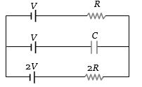
- 6View SolutionIn the given circuit, with steady current, the potential drop across the capacitor must be
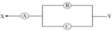
- 7$A, \,B$ and $C$ are voltmeters of resistance $R, \,1 .5R$ and $3R$ respectively as shown in the figure. When some potential difference is applied between $X$ and $Y,$ the voltmeter readings are $V_A, \,V_B$ and $V_C$ respectively. ThenView Solution
- 8View SolutionAssertion : Free electrons always keep on moving in a conductor even then no magnetic force act on them in magnetic field unless a current is passed through it.
Reason : The average velocity of free electron is zero.
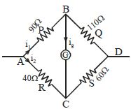
- 9In a Wheatstone bridge, $P = 90\,\Omega $, $Q = 110\,\Omega $ , $R = 40\,\Omega $ and $S = 60\,\Omega $ and a cell of $4\,V\,emf$. Then the potential difference between the diagonal along which a galvanometer is connected is ............. $V$View Solution
- 10In the given figure of meter bridge experiment, the balancing length $AC$ corresponding to null deflection of the galvanometer is $40\,cm$. The balancing length, if the radius of the wire $AB$ is doubled, will be $....cm$View Solution