An inductor 200mH, a capacitor $100\mu\text{F}$ and a resistor $10\Omega$ are connected in series to an a.c. source of 100V, having variable frequency.
- At what frequency of the applied voltage will the power factor of the circuit be 1?
- What will be the current amplitude at this frequency?
- Calculate the Q-factor of the circuit.
Download our app for free and get started
- Since the power factor $\varphi=1$ it means the phase difference between voltage and the current is zero.
$\text{wL}=\frac{1}{\omega\text{C}}$
$\omega^2=\frac{1}{\text{LC}}\Rightarrow\text{v}=\frac{1}{2\pi\sqrt{\text{LC}}}=35.58\text{Hz}$
- Current Amplitude, $\text{I}=\frac{\text{V}_{\text{eff}}}{\text{Z}}=\frac{\text{V}_{\text{eff}}}{\text{R}}=\frac{100}{10}=10\text{A}$ $(\therefore\text{Z = R})$
- Quality factor, $\text{Q}=\frac{1}{\text{R}}\sqrt{\frac{\text{L}}{}\text{C}}=4.47$

Download our appand get started for free
Experience the future of education. Simply download our apps or reach out to us for more information. Let's shape the future of learning together!No signup needed.*
Similar Questions
- 1View SolutionWhen a capacitor is connected in series LR circuit, the alternating current flowing in the circuit increases. Explain why.
- 2When an inductor L and a resistor R in series are connected across a 12 V, 50 Hz supply, a current of 0.5 A flows in the circuit. The current differs in phase from applied voltage by $\pi/3$ radian. Calculate the value of R.View Solution
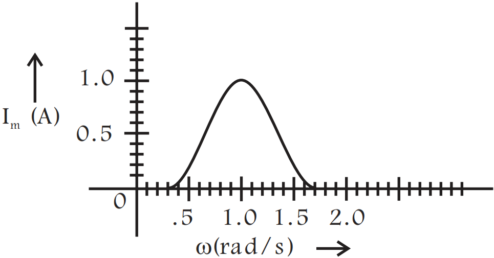
- 3In series LCR circuit, the plot of $I_{max}$ vs $\omega$ is shown in Fig. Find the bandwidth and mark in the figure.View Solution
- 4Derive an expression for the electric field intensity at a point on the equatorial line of an electric dipole of dipole moment $\overrightarrow{\text{P}}$and length 2a. What is the direction of this field?View Solution
- 5View SolutionWrite two important considerations used while fabricating a Zener diode. Explain, with the help of a circuit diagram, the principle and working of a Zener diode as voltage regulator.
- 6View Solution
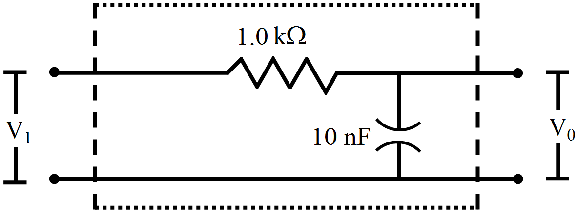
Figure shows a typical circuit for a low-pass filter. An AC input $V_{i }= 10mV$ is applied at the left end and the output $V_0$ is received at the right end. Find the output voltage for ν = 10kHz, 1.0MHz and 10.0MHz. Note that as the frequency is increased the output decreases and, hence, the name low-pass filter.
- 7View SolutionA bulb rated 60W at 220V is connected across a household supply of alternating voltage of 220V. Calculate the maximum instantaneous current through the filament.
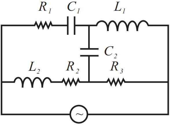
- 8View SolutionDraw the effective equivalent circuit of the circuit shown in Fig, at very high frequencies and find the effective impedance.
- 9An inductor-coil, a capacitor and an AC source of rms voltage 24V are connected in series. When the frequency of the source is varied, a maximum rms current of 6.0A is observed. If this inductor coil is connected to a battery of emf 12V and internal resistance $4.0\Omega,$ what will be the current?View Solution
- 10An AC source of voltage $\text{V = Vm}\sin\omega\text{t}$ is applied across a series LCR circuit. Draw the phasor diagrams for this circuit, when,View Solution
- Capacitive impedance exceeds the inductive impedance.
- Inductive impedance exceeds capacitive impedance.