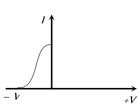
Different voltages are applied across a $P-N$ junction and the currents are measured for each value. Which of the following graphs is obtained between voltage and current
- A
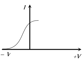
- B
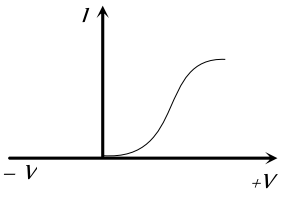
- C
- D
[MP PET 1996; UPSEAT 2002]


Download our appand get started for free
Experience the future of education. Simply download our apps or reach out to us for more information. Let's shape the future of learning together!No signup needed.*
Similar Questions
- 1A common emitter amplifier is designed with NPN transistor $(\alpha= 0.99 ).$ The input impedance is $1 K \Omega$ and load is $10 k \Omega$. The voltage gain will beView Solution
- 2In NPN transistor the collector current is $10\ mA$. If $90 \%$ of electrons emitted reach the collector, thenView Solution
- 3No bias is applied to a $P-N$ junction, then the currentView Solution
- 4View SolutionWhen a semiconductor is heated, its resistance
- 5To obtain a $P$-type germanium semiconductor, it must be doped withView Solution
- 6View SolutionThe voltage gain of a triode depends upon
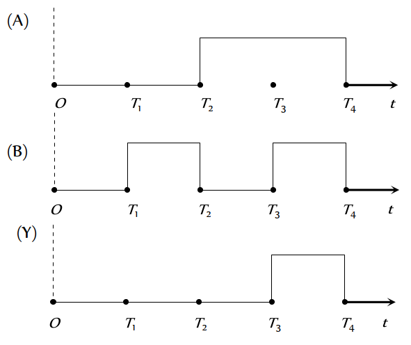
- 7The given figure shows the wave forms for two inputs $A$ and $B$ and that for the output $Y$ of a logic circuit. The logic circuit isView Solution
- 8View SolutionCorrect relation for triode is
- 9Plate resistance of two triode valves is $2 k \Omega$ and $4 k \Omega$, amplification factor of each of the valves is $40.$ The ratio of voltage amplification, when used with $4 k \Omega$ load resistance, will beView Solution
- 10For a common base configuration of $P N P$ transistor $\frac{l_C}{l_E}=0.98$ then maximum current gain in common emitter configuration will beView Solution