In a meter bridge experiment the balance point in obtained if the gaps are closed by $2\,\Omega$ and $3\,\Omega$. A shunt of $x\,\Omega$ is added to $3\,\Omega$ resistor to shift the balancing point by $22.5\,cm$. The value of $X$ is $................$
JEE MAIN 2023, Medium


Download our appand get started for free
Experience the future of education. Simply download our apps or reach out to us for more information. Let's shape the future of learning together!No signup needed.*
Similar Questions
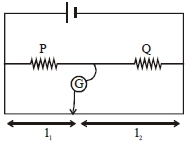
- 1The meter bridge shown is in balanced position with $\frac{\mathrm{P}}{\mathrm{Q}}=\frac{\mathrm{l}_{1}}{\mathrm{l}_{2}}$. If we now litterchange the positions of gavanometer and cell, will the bridge work? If yes, what will be balance condition?View Solution
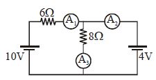
- 2Reading of ammeter $A_1, A_2$ and $A_3$ will be respectivelyView Solution
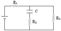
- 3In the circuit here, the steady state voltage across capacitor $C$ is a fraction of the battery $e.m.f.$ The fraction is decided byView Solution
- 4In a meter bridge experiment null point is obtained at $40\, cm$ from one end of the wire when resistance $X$ is balanced against another resistance $Y$. If $X < Y$, then the new position of the null point from the same end, if one decides to balance a resistance of $3X$ against $Y$, will be close to .............. $cm$View Solution
- 5An unknown resistance $R_1$ is connected in series with a resistance of $10 \,\Omega$. This combinations is connected to one gap of a meter bridge while a resistance $R_2$ is connected in the other gap. The balance point is at $50\, cm$. Now, when the $10 \,\Omega$ resistance is removed the balance point shifts to $40\, cm$. The value of $R_1$ is (in $ohm$)View Solution
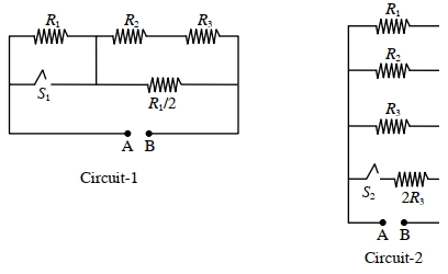
- 6In Circuit-$1$ and Circuit- $2$ shown in the figures, $R_1=1 \Omega, R_2=2 \Omega$ and $R_3=3 \Omega$. $P_1$ and $P_2$ are the power dissipations in Circuit-$1$ and Circuit-$2$ when the switches $S_1$ and $S_2$ are in open conditions, respectively. $Q_1$ and $Q_2$ are the power dissipations in Circuit-$1$ and Circuit-$2$ when the switches $S_1$ and $S_2$ are in closed conditions, respectively.View Solution
Which of the following statement($s$) is(are) correct?
$(A)$ When a voltage source of $6 V$ is connected across $A$ and $B$ in both circuits, $P_1$
$(B)$ When a constant current source of $2 Amp$ is connected across $A$ and $B$ in both circuits, $P_1>P_2$.
$(C)$ When a voltage source of $6 V$ is connected across $A$ and $B$ in Circuit-$1$, $Q_1>P_1$.
$(D)$ When a constant current source of $2 Amp$ is connected across $A$ and $B$ in both circuits, $Q_2$
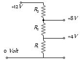
- 7A potential divider is used to give outputs of $4\, V$ and $8\, V$ from a $12\, V$ source. Which combination of resistances, $(R_1, R_2, R_3)$ gives the correct voltages ? $R_1 : R_2 : R_3$View Solution
- 8A current of $1.6\, A$ is flowing through a wire having cross-sectional area $1\, mm^2$. If density of free electrons in the material of the wire is $10^{29}\, per\, m^3$, the drift velocity of electrons will beView Solution
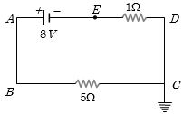
- 9In the given circuit, the potential of the point $E$ isView Solution
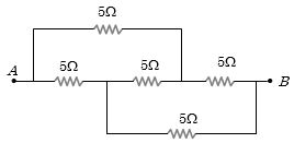
- 10Effective resistance between $A$ and $B$ is ........... $\Omega$View Solution