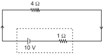
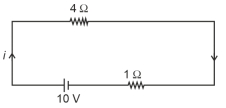
The terminal voltage of the battery, whose emf is $10 \mathrm{~V}$ and internal resistance $1 \Omega$, when connected through an external resistance of $4 \Omega$ as shown in the figure is:
NEET 2024, Medium


Download our appand get started for free
Experience the future of education. Simply download our apps or reach out to us for more information. Let's shape the future of learning together!No signup needed.*
Similar Questions
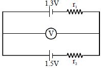
- 1In given diagram ideal voltmeter $V$ reads $1.45\,V$ then relation between $r_1$ and $r_2$ isView Solution
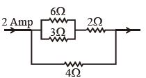
- 2In the adjoining circuit, the potential difference across $3\,\,\Omega $ is ................ $\mathrm{V}$View Solution
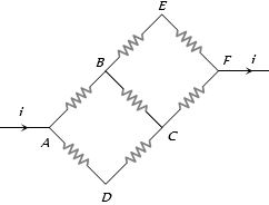
- 3In the adjoining circuit diagram each resistance is of $10$ $\Omega$. The current in the arm $AD$ will beView Solution
- 4The effective resistance of two resistors in parallel is $\frac{{12}}{7}\,\Omega $. If one of the resistors is disconnected the resistance becomes $4$ $\Omega$. The resistance of the other resistor is.............. $\Omega$View Solution
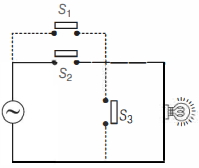
- 5View SolutionConsider the following circuit given below. The bulb will light up, if
- 6Two cells when connected in series are balanced on $8\;m$ on a potentiometer. If the cells are connected with polarities of one of the cell is reversed, they balance on $2\,m$. The ratio of $e.m.f.$'s of the two cells isView Solution
- 7The total momentum of electrons in a straight wire of copper of length $1\, metre$ carrying a current of $16\, A$ isView Solution
- 8A resistor ${R_1}$ dissipates the power $P$ when connected to a certain generator. If the resistor ${R_2}$ is put in series with ${R_1}$, the power dissipated by ${R_1}$View Solution
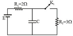
- 9In the circuit shown in the figure $K_1$ is open. The charge on capacitor $C$ in steady state is $q_1$. Now key is closed and at steady state charge on $C$ is $q_2$. The ratio of charges $q_1/q_2$ isView Solution
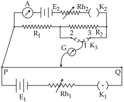
- 10A potentiometer $PQ$ is set up to compare two resistances as shown in the figure. The ameter $A$ in the circuit reads $1.0\, A$ when two way key $K_3$ is open. The balance point is at a length $l_1\, cm$ from $P$ when two way key $K_3$ is plugged in between $2$ and $1$ , while the balance point is at a length $l_2\, cm$ from $P$ when key $K_3$ is plugged in between $3$ and $1$ . The ratio of two resistances $\frac{{{R_1}}}{{{R_2}}}$ is found to beView Solution