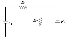
Two resistances ${R_1}$ and ${R_2}$ are joined as shown in the figure to two batteries of $e.m.f.$ ${E_1}$ and ${E_2}$. If ${E_2}$ is short-circuited, the current through ${R_1}$ is
Medium


Download our appand get started for free
Experience the future of education. Simply download our apps or reach out to us for more information. Let's shape the future of learning together!No signup needed.*
Similar Questions
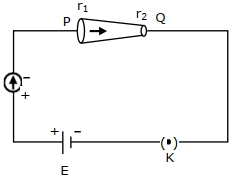
- 1In the given figure, a battery of emf $E$ is connnected across a conductor $P Q$ of length $'Y'$ and different area of cross-sections having radii $r_{1}$ and $r_{2}\left(r_{2}\,<\,r_{1}\right)$.View Solution
Choose the correct option as one moves from $P$ to $Q$ :
- 2A heater coil connected to a supply of a $220\, V$ is dissipating some power ${P_1}.$ The coil is cut into half and the two halves are connected in parallel. The heater now dissipates a power ${P_2}.$ The ratio of power ${P_1}\,\,:\,\,{P_2}$ isView Solution
- 3View SolutionIn the circuit shown in the figure, the current through
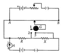
- 4A potentiometer circuit is set up as shown. The potential gradient, across the potentiometer wire, is $k$ $volt/cm$ and the ammeter, present in the circuit, reads $1.0\,\, A$ when two way key is switched off. The balance points, when the key between the terminals $(i)$ $1$ and $2$ $(ii)$ $1$ and $3,$ is plugged in, are found to be at lengths $l_1$ and $l_2$ respectively. The magnitudes, of the resistors $R$ and $X,$ in $ohms$, are then, equal, respectively, toView Solution
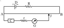
- 5In the given potentiometer circuit, the resistance of the potentiometer wire $AB$ is $R_0$. $C$ is a cell of internal resistance $r$. The galvanometer $G$ does not give zero deflection for any position of the jockey $J$. Which of the following cannot be a reason for this?View Solution
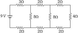
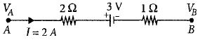
- 6The potential difference $(V_A - V_B)$ between the points $A$ and $B$ in the given figure is ............ $V$View Solution
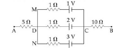
- 7In the circuit shown, the potential difference between $A$ and $B$ is ............. $V$View Solution
- 8In the circuit as shown in the figure, the heat produced by $6\, ohm$ resistance due to current flowing in it is $60$ calorie per second. The heat generated across $3\, ohm$ resistance per second will be ................. $calorie$View Solution
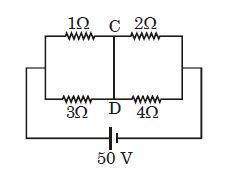
- 9In the given circuit diagram, find the current passing through wire $CD$ (in ampere)View Solution
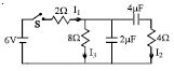
- 10In the circuit shown in the figure, the switch $S$ is initially open and the capacitor is initially uncharged. $ I_1, I_2$ and $I_3$ represent the current in the resistance $2\,\Omega , 4\,\Omega $ and $8\,\Omega$ respectively.View Solution