Question
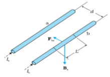
  1. Two straight long parallel conductors carry currents $I_1$ and $I_2$ in the same direction. Deduce the expression for the force per unit length between them.
Depict the pattern of magnetic field lines, around them.
  1. A rectangular current carrying loop EFGH is kept in a uniform magnetic field as shown in the figure.
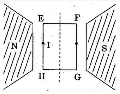
  1. What is the direction of the magnetic moment of the current loop?
  2. When is the torque acting on the loop (A) maximum, (B) zero?

Answer

Derivation of force per unit length:

Figure shows two long parallel conductors a and b separated by a distance d and carrying (parallel) currents $I_$a and $I_b,$ respectively. The conductor ‘a’ produces, the same magnetic field $B_a$ at all points along the conductor ‘b’. The right-hand rule tells us that the direction of this field is downwards (when the conductors are placed horizontally). From Ampere’s circuital law, its magnitude is given by
$\text{B}_{a} = \frac{\mu_{0}\text{I}_{a}}{2\pi\text{d}}$
The conductor ‘b’ carrying a current $I_b$ will experience a sideways force due to the field $B_a$. The direction of this force is towards the conductor ‘a’. We label this force as $F_{ba}$, the force on a segment L of ‘b’ due to ‘a’. The magnitude of this force is given by.
$\text{F}_{ba} = \text{I}_{b }\text{L B}_{a} = \frac{\mu_{0}\text{I}_{a}\text{I}_{b}}{2\pi\text{d}}\text{L}$
Let $f_{ba}$ represent the magnitude of the force $F_{ba}$ per unit length. Then, from the above equation
$\text{f}_{ba} = \frac{\mu_{0}\text{I}_{a}\text{I}_{b}}{2\pi\text{d}}$
Pattern of Magnetic Field lines:
    1. Direction of magnetic moment $\overrightarrow{\text{M}}$ of the current loop is perpendicular to the plane of the page and directed downwards.
      1. Torque acting on the loop is maximum when $\overrightarrow{\text{M}}$ is perpendicular dicular to $\overrightarrow{\text{B}}.$
      2. It is minimum when $\overrightarrow{\text{M}}$ is parallel to $\overrightarrow{\text{B}}.$

Need a full question paper?

Generate a complete, print-ready paper with questions like this in minutes — across 16+ boards, with answer keys.

Start Generating Free

Similar questions

The $\text{K}_\alpha$ and $\text{K}_\beta$ X-rays of molybdenum have wavelengths 0.71A and 0.63A respectively. Find the wavelength of $\text{L}_\alpha$ X-ray of molybdenum.
A room has AC run for 5 hours a day at a voltage of 220V. The wiring of the room consists of Cu of 1mm radius and a length of 10m. Power consumption per day is 10 commercial units. What fraction of it goes in the joule heating in wires? What would happen if the wiring is made of aluminium of the same dimensions?
$[\rho _{cu} = 1.7 \times 10^{-8}_{Ωm} , \rho _{Al} = 2.7 \times 10^{-8} Ωm]$
Poynting vectors S is defined as a vector whose magnitude is equal to the wave intensity and whose direction is along the direction of wave propogation. Mathematically, it is given by $\text{S}=\frac{1}{\mu_0}\text{E}\times\text{B}$. Show the nature of S vs t graph.
Figure shows a series LCR circuit connected to a variable frequency 230V source. L = 5.0H, C = 80μF, R = 40Ω.
  1. Determine the source frequency which drives the circuit in resonance
  2. Obtain the impedance of the circuit and the amplitude of current at the resonating frequency.
  3. Determine the rms potential drops across the three elements of the circuit. Show that the potential drop across the LC combination is zero at the resonating frequency.
The blocks shown in figure have equal masses. blocks in the process. The surface of A is smooth but that of B has a friction coefficient of 0.10 with the floor. Block A is moving at a speed of 10m/s towards B which is kept at rest. Find the distance travelled by B if
  1. The collision is perfectly elastic
  2. The collision is perfectly inelastic. $($Take $g = 10m/s^2)$
  1. Draw a circuit diagram to study the input and output characteristics of an n-p-n transistor in its common emitter configuration. Draw the typical input and output characteristics.
  2. Explain, with the help of a circuit diagram, the working of n-p-n transistor as a common emitter amplifier.
Figure. shows a large closed cylindrical tank containing water. Initially the air trapped above the water surface has a height $h_0$ and pressure $2p_0$ where $p_0$ is the atmospheric pressure. There is a hole in the wall of the tank at a depth $h_1$ below the top from which water comes out. A long vertical tube is connected as shown.
  1. Find the height $h_2$ of the water in the long tube above the top initially.
  2. Find the speed with which water comes out of the hole.
  3. Find the height of the water in the long tube above the top when the water stops coming out of the hole.
The emf $\in$ and the internal resistance r of the battery, shown in the figure. are 4.3V and $1.0\Omega$ respectively. The external resistance R is $50\Omega.$ The resistances of the ammeter and voltmeter are $2.0\Omega$ and $200\Omega$ respectively. (a) Find the readings of the two $200\Omega$ respectively. (a) Find the readings of the two meters. (b) The switch is thrown to the other side. What will be the readings of the two meters now?
Draw the labelled ray diagram for the formation of image by a compound microscope.Derive the expression for the total magnification of a compound microscope. Explain why both the objective and the eyepiece of a compound microscope must have short focal lengths.
Two circular coils of radii 5.0cm and 10cm carry equal currents of 21 A. The coils have 50 and 100 turns reepectively and are placed in such a way that their planes as well as the centres coincide. Find the magnitude of the magnetic field B at the common centre of the coils if the currents in the coils are (a) in the same sense (b) in the opposite sense.