Using truth tables of AND gate and NOT gate show that NAND gate is an AND gate followed by a NOT gate. Hence write the truth table of NAND gate.
Why are NAND gates called ‘Universal Gates’?
Why are NAND gates called ‘Universal Gates’?
CBSE OUTSIDE DELHI - SET 1 GUHAWATI 2015
Download our app for free and get started
| A | B | Output of AND gate (Input of NOT gate) |
Output of NOT gate |
| 0 | 0 | 0 | 1 |
| 0 | 1 | 0 | 1 |
| 1 | 0 | 0 | 1 |
| 1 | 1 | 1 | 0 |
| Truth table of NAND Gate | ||
| A | B | Y |
| 0 | 0 | 1 |
| 0 | 1 | 1 |
| 1 | 0 | 1 |
| 1 | 1 | 0 |

Download our appand get started for free
Experience the future of education. Simply download our apps or reach out to us for more information. Let's shape the future of learning together!No signup needed.*
Similar Questions
- 1View SolutionA series LCR circuit with R = 20Ω, L = 1.5H and C = 35μF is connected to a variable-frequency 200V ac supply. When the frequency of the supply equals the natural frequency of the circuit, what is the average power transferred to the circuit in one complete cycle?
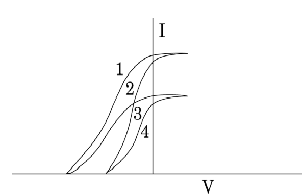
- 2View SolutionThe given graph shows the variation of photo-electric currently) with the applied voltage(V) for two different materials and for two different intensities of the incident radiations. Identify and explain using Einstein's photo electric equation the pair of curves that correspond to (i) different materials but same intensity of incident radiation (ii) different intensities but same materials.
- 3An inductor 200mH, a capacitor $100\mu\text{F}$ and a resistor $10\Omega$ are connected in series to an a.c. source of 100V, having variable frequency.View Solution
- At what frequency of the applied voltage will the power factor of the circuit be 1?
- What will be the current amplitude at this frequency?
- Calculate the Q-factor of the circuit.
- 4View Solution
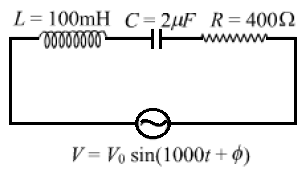
- Find the value of the phase difference between the current and the voltage in the series LCR circuit shown below. Which one leads in phase: current or voltage?
- Without making any other change, find the value of the additional capacitor $C_1,$ to be connected in parallel with the capacitor C, in order to make the power factor of the circuit unity.
- 5Use Bohr's postulates hydrogen atom to deduce the expression for the kinetic energy (K.E.) of the electron revolving in the $\mathrm{n}^{\text {th }}$ orbit and show that, K.E. $\frac{\mathrm{e}^2}{8 \pi \varepsilon_0 e_n}$, where $r_n$ is the radius of the $n^{\text {th }}$ orbit. How is the orbit. How is the potential energy in the orbit related to the orbital radius orbit related to the orbital radius $r_n$ ?View Solution
- 6View SolutionObtain the answers (a) to (b) in Exercise 7.13 if the circuit is connected to a high frequency supply (240V, 10kHz). Hence, explain the statement that at very high frequency, an inductor in a circuit nearly amounts to an open circuit. How does an inductor behave in a dc circuit after the steady state?
- 7In a series LCR circuit connected to an ac source of variable frequency and voltage v $v_m= \sin, $ draw a plot showing the variation of current (I) with angular frequency ($\omega$) for two different values of resistance R1 and R2(R1 > R2 ). Write the condition under which the phenomenon of resonance occurs. For which value of the resistance out of the two curves, a sharper resonance is produced? Define Q-factor of the circuit and give its significance.View Solution
- 8View Solution
- Name the phenomenon on which the working of an optical fibre is based.
- What are the necessary conditions for this phenomenon to occur?
- Draw a labelled diagram of an optical fibre and show how light propagates through the optical fibre using this phenomenon.
- 9A sinusoidal voltage of peak value $283 V$ and frequency $50 Hz$ is applied to a series $L C R$ circuit in which $R =3 \Omega, L=25.48 mH$, and $C =796 \mu F$. Find (a) the impedance of the circuit; (b) the phase difference between the voltage across the source and the current; (c) the power dissipated in the circuit; and (d) the power factor.View Solution
- 10A resistance R and a capacitor C are connected in series to a source $\text{V}=\text{V}_0\sin\omega\text{t}.$View Solution
Find:- The peak value of the voltage across the (i) resistance and (ii) capacitor.
- The phase difference between the applied voltage and current. Which of them is ahead?