| Interference | Diffraction |
|
|
| Interference | Diffraction |
|
|

$ = \frac{4\text{C}}{3} = \frac{40}{3}\mu\text{F}$
$ = 5\times10^{-3}\text{C} = 5 \text{mC}$
$\text{Charge on } \text{C}_ {1},\text{C}_{2},\text{C}_{3}\text{ is same and is equal to } \frac{\text{C}}{3}\times\text{V}$
$ = \frac{5}{3}\times10^{-3}\text{C}$
$ = 1.67\text{mC}$.

$\varphi = \frac{\text{total enclosed charge }}{\in_{0}}$
Net charge enclosed inside the shell q = 0
$\therefore$ Electric flux through the shell $\frac{\text{q}}{\in_{o}} = 0 $
even when the student writes - Electric flux through the shell is zero as electric field inside the shell is zero.
Alternate Answer
$\oint\overrightarrow{\text{E}}.\overrightarrow{\text{d}S} = \frac{\text{q}}{\text{E}_{o}}$
$\text{F}_{A} = \frac{1}{4\pi\text{E}_{o}}\frac{2\text{Q}(\text{Q} + \text{Q} / 2)}{\text{x}^{2}}$
$ = \frac{1}{4\pi\text{E}_{o}}\frac{3\text{Q}^{2}}{\text{x}^{2}}$.
$ = \frac{500\times10^{-9}\times1}{10^{-3}}$
= 0.5 mm or 5 x 10⁻⁴ m
$\text{a} = \frac{2\times500\times10^{-9}\times1}{10\times5\times10^{-4}}$
𝑎 =2 ×10⁻⁴ m or 0.2 mm.
$\text{I} = \frac{220}{\sqrt{100^{2} + \bigg(\frac{1}{\frac{100}{\pi}\times10^{-6}\times2\pi\times50}}\bigg)^{2}}$
$ = \frac{2.2}{\sqrt{2}}\text{A} = 1.55\text{A}$
$ = 155 \text{ volt}$
Voltage across the capacitor $ = 100\times1.55 \text{V}$
$ = 155 \text{ volt}$
Yes,
The sum of the two voltages is greater than 220 V but the voltage across the resistor and the capacitor are not in phase.

For an ideal inductor, $\phi = \frac{\pi}{2}$
$\therefore\text{P}_{av} = \text{l}_{av} \text{x } \text{ e}_{av}\cos\frac{\pi}{2}$
$\text{P}_{av} = 0 .$
Because as iron rod is inserted inductance increases. Thus, current decreases and brightness decreases.
(The battery remains connected to the capacitors)
Alternate Answer
Alternate Answer
$\omega\text{L} = \frac{1}{\text{wc}}(\text{or } \phi = 0).$Also, $\text{C}_{parallel} =( 3 + 3 +3 ) =9 \mu\text{F}$
Energy stored $ = \frac{1}{2}\text{CV}^{2}$
$\therefore$Energy in series combination $ =\frac{1}{2}1 \times10^{-6}\times\text{V}^{2}$
Energy in parallel combination $ =\frac{1}{2}9 \times10^{-6}\times\text{V}^{2}$
$\therefore$ Ratio = 1:9.
Band gap should be 1.8 eV to 3 eV These materials have band gap which is suitable to produce desired visible light wavelengths.
$\oint\text{B}.\text{ds} = 0 $
$\oint\text{E}.\text{ds} = \frac{\text{q}}{\in_{o}}$/The net electric flux through any closed surface is $\frac{1}{\in_{o}}$ times the net charge.
which indicates magnetic monopoles do not exist/ magnetic poles always exists in pairs.


Alternate Answer
$\text{I} =\frac{\text{V}}{(\text{R} / 2 )}$ And $\text{E} = \text{V} - \text{I}(\text{r}/ 2 )$ This gives $\text{I} = \frac{1.4}{7/2}\text{A} = 0.4\text{A}$ $\therefore\frac{\text{r}}{2} = \frac{1.5 - 1.4}{0.4} = 0.25$ $\therefore\text{r} = 0.5\Omega$.

If N is the number of nuclei left over at t=t, we have
$\frac{-\text{dN}}{\text{dt}}\propto\text{N}$
Or $\frac{-\text{dN}}{\text{dt}} = \lambda\text{N}(\lambda =\text{decay constant })$
$\therefore\frac{\text{dN}}{\text{N}} = -\lambda\text{dt}$
Or $l \text{nN} = - \lambda\text{t} + constant $
$\therefore \text{ At } \text{t} = 0 , $ we have
$l\text{nN}_{0} = constant $
$l \text{nN} = - \lambda\text{t} + l\text{nN}_{0}$
Or $l\text{n}(\frac{\text{N}}{\text{N}_{0}}) = -\lambda\text{t}$
$\therefore \text{N} = \text{N}_{0}\text{e}^{-\lambda\text{t}}$
Alternate Answer
$\tau = \frac{1}{\lambda}$.
| A | B | Output of AND gate (Input of NOT gate) | Output of NOT gate |
| 0 | 0 | 0 | 1 |
| 0 | 1 | 0 | 1 |
| 1 | 0 | 0 | 1 |
| 1 | 1 | 1 | 0 |
| Truth table of NAND Gate | ||
| A | B | Y |
| 0 | 0 | 1 |
| 0 | 1 | 1 |
| 1 | 0 | 1 |
| 1 | 1 | 0 |
NAND gate is called universal gate because all other basic gates like AND, OR, NOT gate, can be realised by using NAND gates only.


Alternate Answer
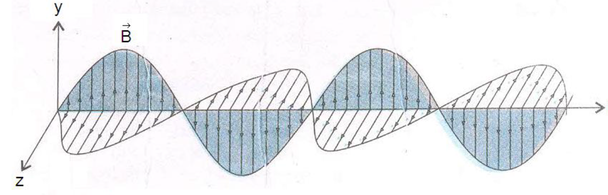
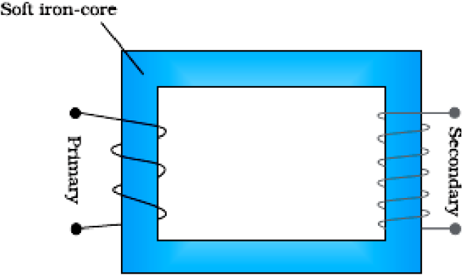
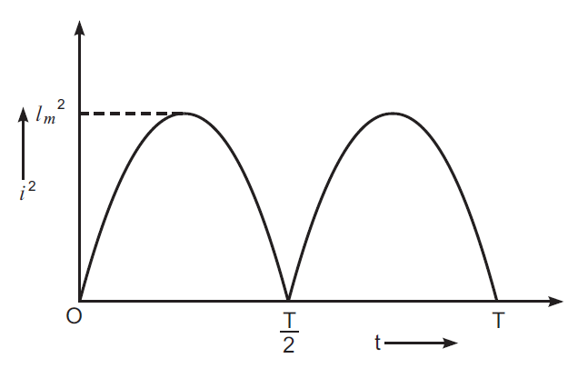
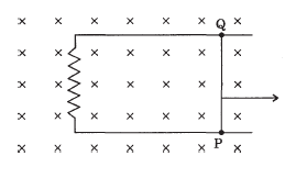
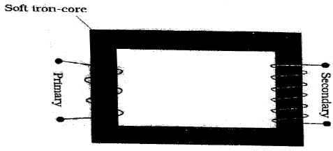
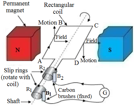
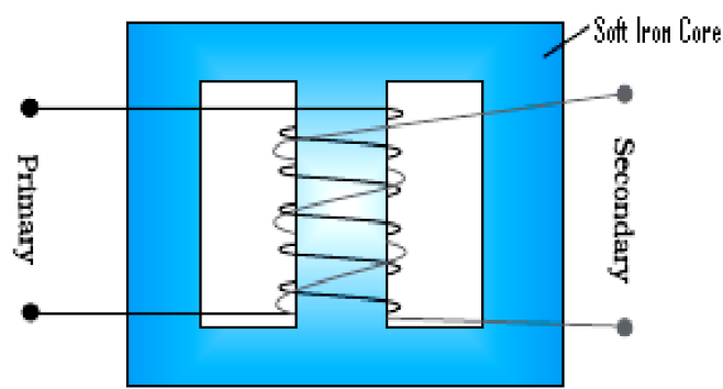
When the current through the primary coil changes, the magnetic flux through the secondary changes. This produces an induced emf in the secondary coil/it works on mutual induction. $\varepsilon_{s} = -\text{N}_{s}\frac{\text{d}\varphi}{\text{dt}}$ $\varepsilon_{p} = -\text{N}_{p}\frac{\text{d}\varphi}{\text{dt}}$ $\frac{\varepsilon_{s}}{\varepsilon_{p}} = \frac{\text{N}_{s}}{\text{N}_{p}}$ $i_{s}\varepsilon_{s} = i_{p} \varepsilon_{p}$ (for ideal transformer) $\frac{i_{s}}{i_{p}} = \frac{\varepsilon_{p}}{\varepsilon_{s}}.$


Conclusions:
Alternate Answer
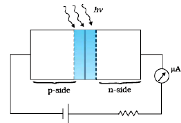
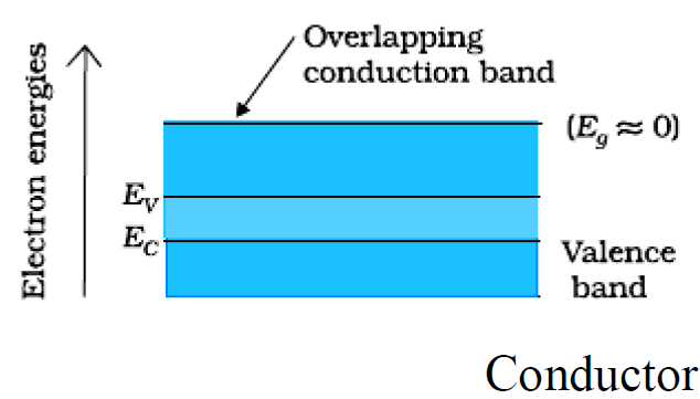
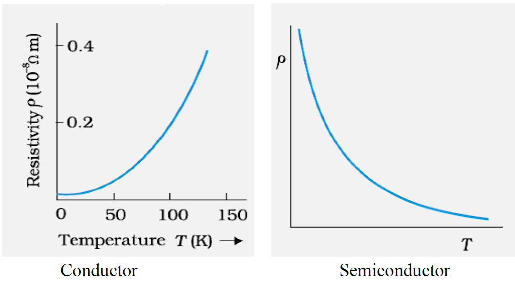
In conductor with increase in temperatures, relaxation time decreases, but number density of charge carriers is not dependent on temperature. Hence,$\rho$ increases. In semiconductors number density of charge carriers increases with temperature, it dominates the decrease in relaxation time. Hence, $\rho$ decreases.Average power consumed in resistor R
$\text{P}_{av} = \frac{1}{\int_{0}^{T}\text{dt}}.\int_{0}^{T}\text{i}^{2}\text{R dt}$
$ = \frac{\text{i}_{m}^{2}\text{R}}{\text{T}}\int_{0}^{T}\sin^{2}\omega\text{t }\text{ dt} - - - - - (1)$
$ = \frac{\text{i}_{m}^{2}\text{R}}{2\text{T}}\int_{0}^{T}(1 -\cos2\omega\text{t})\text{dt}$

$ = \frac{\text{i}_{m}^{2}\text{R}}{2\text{T}}\bigg[\int_{0}^{T}\text{dt} - \int_{0}^{T}\cos2\omega\text{t }\text{ dt}\bigg] - - - - - (2)$
$ =\frac{\text{i}_{m}^{2}\text{R}}{2\text{T}}[\text{T} - 0 ]$
$ = \frac{\text{i}_{m}^{2}\text{R}}{2}$
$\text{P}_{av} =\frac{\text{V}_{rms}^{2}}{\text{R}} = \frac{\text{V}_{eff}^{2}}{\text{R}}$
$\Rightarrow\text{R} = \frac{\text{V}_{rms}^{2}}{\text{P}_{av}}$
$ = \frac{220\times220}{100}$
$ = 484\Omega.$
Resultant potential across LCR
$\text{V}^{2} = \text{V}^{2}_{\text{R}} + (\text{V}_{L} - \text{V}_{c} ) ^{2}$
$\text{V}_{R} = \text{iR},\text{V}_{L} = \text{i}\text{X}_{L},\text{V}_\text{c} = \text{i X}_{c}$
On solving
$\text{Z} = \sqrt{\text{R}^{2} + (\text{X}_{L} - \text{X}_{C})^{2}}$
With increase in ω, current first increases (up to ωo ) and then decreases.
Method – I
$\text{Z} =\text{E}/\text{I}$
Calculation of $\text{Z} =\frac{12}{0.5}= 24\Omega$
$\cos\phi = \frac{\text{R}}{\text{Z}}$
Calculation of R = 12Ω.
Method – II
$\text{Z} = \text{E}/\text{I}$
Z = 24Ω
$\tan \phi = \frac{\text{X}_{L}}{\text{R}}$
R = 12Ω.

Method I
$\text{E} = \text{B} $ 1 v
$\text{I} =\frac{\text{B1v}}{\text{R}} = \text{I} = 0.5\text{A}$
$\text{F} = \text{B}$ I 1
Calculation of $\text{F} = 3.75\times10^{-3}\text{N}$.
Method II
$\text{F} = \frac{\text{B}^{2}1^{2}\text{v}}{\text{R}}$
Correct substitution and calculation of $\text{F} = 3.75\times10^{-3}\text{N}$.

$X_C=\frac{1}{\omega C}=\bigg(\frac{1}{1000\times2\times10^{-6}}\bigg)\Omega=500\Omega$
Phase angle
$\tan\Phi=\frac{X_L-X_C}{R}$
$\tan\Phi=-\frac{\pi}{4}$
As $X_C>X_L$ (phase angle is negative), hence current leads voltage
$X_{C'}>X_L$
$\frac{1}{WC'}=100$
$C'=10\mu\text{F}$
$C'=C+C_1$
$10=2+C_1$
$C_1=8\mu\text{F}$
$\text{X}_{L} = \omega_{L}$
As number of turns decreases, L decreases, hence current through bulb increases. /voltage across bulb increases.
Iron rod increases the inductance, which increases XL, hence½ current through the bulb decreases/voltage across bulb decreases.
condition (XC = XL) the current through the bulb will become maximum/increase.
In a series LCR circuit connected to an ac source of variable frequency and voltage v vm= sin, draw a plot showing the variation of current (I) with angular frequency ($\omega$) for two different values of resistance R1 and R2(R1 > R2 ). Write the condition under which the phenomenon of resonance occurs. For which value of the resistance out of the two curves, a sharper resonance is produced? Define Q-factor of the circuit and give its significance.


$ = \frac{1}{\sqrt{5\times80\times10^{-6}}} = 50\text{radian / s }$
$\text{I}_{rms} = \frac{\text{V}_{rms}}{\text{R}} = \frac{240}{40}\text{A} = 6\text{A}$
$\text{V}_{rms} = \text{I}_{rms}\text{X}_{c}$
$ = 6\times\frac{1}{50\times80\times10^{-6}}\text{V}$
$ = \frac{6\times10^{6}}{4\times10^{3}}\text{V} = \frac{6000}{4}\text{V} = 1500\text{V}.$
$ = \frac{1}{\sqrt{200\times10^{-3}\times500\times10^{-6}}} = 100 \text{ radian s }^{-1}$
$\big(\text{or } \text{ v} = \frac{\omega}{2\pi} = \frac{50}{\pi} \text{Hz}\approx51.9\text{Hz})$
= 2.
Where $\text{Z} = \sqrt{\text{R}^{2}+ \big(\text{X}_{L} - {\text{X}_{C}}\big)^{2}}$
$\frac{\text{cos}\phi_B}{\text{cos}\phi_A}$ $ = \frac{\text{Z}_A}{\text{Z}_{B}}$ $=\frac{\sqrt{\text{R}^{2}_{A} + \text{X}}_{L_{A}}^{2}}{\sqrt{\text{R}_{B}^{2}+\big(\text{X}_{L_{B}}-\text{X}_{C_{B}}}\big)^{2}}$
$=\frac{\text{R}\sqrt{10}}{\text{R}\sqrt{5}} = \sqrt{2}$

Principle: When alternating current flows through the primary, the magnetic flux linked with the secondary changes. As a result, an e.m.f. is induced in it.
Alternate Answer
It works on the principle of Mutual Induction.
Working: Change of flux is zero for d.c.
$=\frac{\text{V}_0\text{R}}{\sqrt{\text{R}^2+\omega^2\text{L}^2}}$
Voltage drop accurs, reduse,
$=1\text{X}_\text{L}$
$=\frac{(\omega\text{L)}}{\sqrt{\text{X}^2+\omega^2\text{L}^2}}$
$\tan\theta=\frac{\text{X}_\text{L}}{\text{R}}$
And resistance lead to the Inductance.
$\text{I}_0=\frac{\text{V}_0}{\sqrt{\text{R}^2+\text{X}^2_\text{c}}}$
$\phi=\tan^{-1}\Big(\frac{\text{V}_\text{C}}{\text{V}_\text{R}}\Big)=\tan^{-1}\Big(\frac{\text{X}_\text{C}}{\text{R}}\Big)=$ Phase difference between V & I is ahead of V.