Questions

[5 marks Questions]

🎯

Test yourself on this topic

9 questions · timed · auto-graded

Question 15 Marks
What is electrical resistivity of a material? What is its unit? Describe an experiment to study the factors on which the resistance of conducting wire depends.
Answer
The inherent property of a conductor because of which it resists the flow of electric current is called resistivity. Resistivity for a particular material is unique. The SI unit of resistivity is (Ohm metre).Experiment to study the factors on which resistance of conducting wire depends:
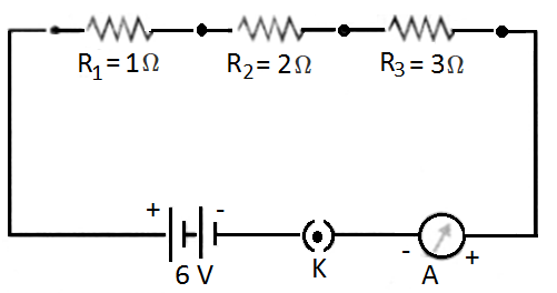
  • Take an ammeter, electric cell, plug key, nichrome wire and wires of different materials.
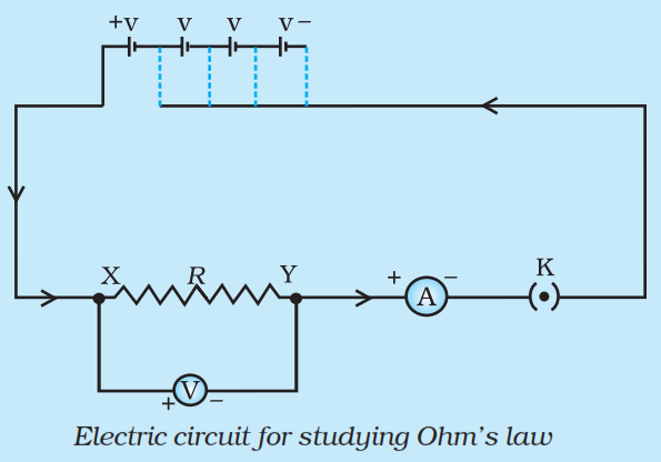
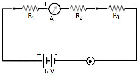
  • Make the circuit as shown in figure.
  • Start the experiment with nichrome wire. Attach it in the circuit and take ammeter reading.
  • Change the length of nichrome wire and take ammeter reading.
  • Change the thickness of nichrome wire and take ammeter reading.
  • After above steps, use copper wire for the experiment. Attach a copper wire in the circuit and take ammeter reading.
  • Change the length of copper wire and take ammeter reading.
  • Change the thickness of copper wire and take ammeter reading.
  • Repeat above steps with wires of different materials.
Observations:
  • It is seen that resistance depends on material of conductor.
  • Resistance depends on length of conductor.
  • Resistance depends on area of cross-section.
View full question & answer
Question 25 Marks
Three $2\Omega$ resistors, A, B and C, are connected as shown in Figure. Each of them dissipates energy and can withstand a maximum power of 18W without melting. Find the maximum current that can flow through the three resistors?
Answer
Here, $P =18 W$
Using, $P=I^2 R$, we get
$I=\sqrt{\frac{P}{R}}=\sqrt{\frac{18}{2}}=\sqrt{9}=3 A$
$\therefore$ Maximum current that can flow through a resistor $A=3 A$
Since resistors B and C are connected in parallel, so potential difference across B and C is same. Let $I _1$, be the current flowing through resistor. B and $I _2$ be the current flowing through resistor C ,
$\therefore I_1 R_1=I_2 R_2$
or $\frac{ I _1}{ I _2}=\frac{ R _2}{ R _1}=\frac{2 \Omega}{2 \Omega}=1$
or, $I _1= I _2$
But $I _1+ I _2= I =3$
$\therefore 2 I_1=3 \text { or } I_1=1.5 A$
and $I _2= I _1=1.5 A$
View full question & answer
Question 35 Marks
State Ohm’s law? How can it be verified experimentally? Does it hold good under all conditions? Comment.
Answer
According to Ohm's law the electric current flowing through a conductor is directly proportional to the potential difference applied across its ends provided the physical conditions such as temperature etc remains unchanged. Let V be the potential difference applied across the ends of conductor through which current Iflows, then according to Ohm's law.$\text{V}\propto\text{I}\Rightarrow\ \text{V}=\text{IR}$
Ohm’s law can be verified experimentally by the activity given below:
  1. Firstly, Set up a circuit as shown in figure given below, consisting of a nichrome wire XY of length, say 0.5m, an ammeter, a voltmeter and four cells of 1.5V each. (Nichrome is an alloy of nickel,chromium, manganese, and iron metals.)
  1. First use only one cell as the source in the circuit. Note the reading in the ammeter I, for the current and reading of the voltmeter V for the potential difference across the nichrome wire XY in the circuit. Tabulate them in the Table given.
  2. Next connect two cells in the circuit and note the respective readings of the ammeter and voltmeter for the values of current through the nichrome wire and potential difference across the nichrome wire.
  3. Repeat the above steps using three cells and then four cells in the circuit separately.
  4. Calculate the ratio of V to I for each pair of potential difference V and current I.
S.No. Number of cells used in the circuit Current through the nichrome wire, I (ampere) Potential difference across the nichrome wire, V (Volt) $\frac{\text{V}}{\text{I}}$ $\Big(\frac{\text{Volt}}{\text{Ampere}}\Big)$
1. 1      
2. 2      
3. 3      
4. 4      
  1. Plot a graph between V and I. The graph will be a straight line as shown below.
  1. This verifies the Ohm’s law.
Ohm's does not hold under all conditions as it is basically not a fundamental law which means it has exceptions. Following are the conditions when Ohm’s law does not hold:
  • It is not obeyed when physical conditions of conductors like temperature keep on changing.
  • It is not obeyed by a lamp filament, junction diode, thermistor etc.
  • It is not obeyed in case of superconductors whose resistance is equal to zero.
View full question & answer
Question 45 Marks
$B_1, B_2$ and $B_3$ are three identical bulbs connected as shown in Figure. When all the three bulbs glow, a current of 3 A is recorded by the ammeter A
.
i. What happens to the glow of the other two bulbs when the bulb $B_1$ gets fused?
ii. What happens to the reading of $A_1, A_2, A_3$ and $A$ when the bulb $B_2$ gets fused?
iii. How much power is dissipated in the circuit when all the three bulbs glow together?
Answer
i. The glow of bulb depends upon the energy disspated per second i.e. $P =\frac{ V ^2}{ R }$. Since V and R of both the bulbs $B_2$ and $B_3$ remain the same even if bulb $B$, gets fused so glow of $B_2$ and $B_3$ remain the same.
ii. Since bulbs are identical, so their resistance is equal (i.e. resistance of each bulb $=R \Omega$ ).
When all bulbs glow, net resistnace of the circuit is given by,
$\frac{1}{R^{\prime}}=\frac{1}{R}+\frac{1}{R}+\frac{1}{R}=\frac{3}{R}$
Or, $R ^{\prime}=\frac{ R }{3}$
$I=3 A, V=4.5 V$
Using, $V= R ^{\prime}$, we get
$4.5=3 \times \frac{R}{3} \text { or } R=4.5 \Omega$
When $B _2$ gets fused, only two bulbs $B _1$ and $B _2$ in parallel are in the circuit.
$\therefore$ Net resistance of the circuit is given by,
$\frac{1}{R}=\frac{1}{4.5}+\frac{1}{4.5}=\frac{2}{4.5} \text { or } R=\frac{4.5}{2} \Omega$
$\therefore I=\frac{V}{R}=\frac{4.5 \times 2}{4.5}=2 A$
Thus, reading of ammeter $A=2 A$
Since $B_1$ and $B_3$ are in parallel and have same resistance, so $2 A$ current will be equally distributed between $B_1$ and $B_3$. Therefore, reading of ammeter $A_1=1 A$ Reading of ammeter $A_3=1 A$ Circuit containing $B_2$ is broken, so no current flows through this circuit. Hence reading of ammeter $A_2=$ zero.
iii. Power dissipated in the circuit,
$P=V \times I$
$=4.5 \times 3=13.5 W$
View full question & answer
Question 55 Marks
What is Joule’s heating effect? How can it be demonstrated experimentally? List its four applications in daily life.
Answer
The Joule’s Law of Heating states that the heat produced in a resistor is:
  1. Directly proportional to the square of current for a given resistor.
  2. Directly proportional to resistance for a given current, and
  3. Directly proportional to the time for which the current flows through the resistor.
This can be expressed by following equation:
$H=I^2 R t$
Here; I is electric current, R is resistance, t is time and H is heating effect.
Experiment to Demonstrate Joule’s Law of Heating:
  • In this experiment, we will show the effect of current on heating.
  • Take a water heating immersion rod and connect to a socket which is connected to regulator. It is important to recall that a regulator controls the amount of current flowing through a device.
  • Keep the pointer of regulator on minimum and count the time taken by immersion rod to heat a certain amount of water.
  • Increase the pointer of regulator to next level. Count the time taken by immersion rod to heat the same amount of water.
  • Repeat above step for higher levels on regulator to count the time.
Observation: It is seen that with increased amount of electric current, less time is required to heat the same amount of water. This shows Joule’s Law of Heating. Application: Electric toaster, oven, electric kettle and electric heater etc. work on the basis of heating effect of current.
View full question & answer
Question 65 Marks
How will you conclude that the same potential difference (voltage) exists across three resistors connected in a parallel arrangement to a battery?
Answer

Perform an activity to investigate the relation between potential difference across parallel combination of resistors and the potential difference across each individual resistors,
  1. Connect three resistors of resistances $R _1, R _2$ and $R _3$ in parallel. One end of each resistor is joined at a common point ‘a’ and the other end of each resistor is connected at another common point ‘b’.
  2. Connect the parallel combination of resistors with a battery, a plug key K and an ammeter A as shown in figure.
  1. Now connect a voltmeter across the parallel combination of resistors between a and b points.
  2. Note the reading of voltmeter. Let it be V. This is the potential difference across the parallel combination of resistors.
  3. Now, disconnect the voltmeter and connect it across $R_1$ as shown in figure.
  1. Note the reading of voltmeter. It is found to be V.
  2. Disconnect the voltmeter and connect it across $R _2$. Note the reading of voltmeter. It is found to be V .
  3. Again disconnect the voltmeter and connect it across $R _3$. Note the reading of voltmeter. It is found to be V .
Conclusion: When resistors are connected in parallel to each other, potential difference across each resistor is equal to the potential difference across the parallel combination of resistors.
View full question & answer
Question 75 Marks

Find out the following in the electric circuit given in Figure.
  1. Effective resistance of two 8Ω resistors in the combination.
  2. Current flowing through 4Ω resistor.
  3. Potential difference across 4Ω resistance.
  4. Power dissipated in 4Ω resistor.
  5. Difference in ammeter readings, if any.
Answer
  1. Two 80 resistors are in parallel, so their effective resistance is given by,
$\frac{1}{\text{R}}=\frac{1}{8}+\frac{1}{8}=\frac{1}{4}\ \text{or R }=4\Omega$
  1. Net resistance of the circuit, $\text{R}=4\Omega+4\Omega=8\Omega$
$\text{V}=8\text{V}$
$\therefore$ Current in the circuit, $\text{I}=\frac{\text{V}}{\text{R}}=\frac{8}{8}=1\text{A}$
Hence current flowing through $4\Omega$ resistor = 1A
  1. Potential difference across $4\Omega$ resistor, V = IR
= 1 × 4 = 4V
  1. d. Power dissipated in $4 \Omega$ resistor, $P=I^2 R$
= 1 × 4 = 4W
  1. Since same current flows through every part in a series circuit and both the ammeters are connected in series, so there will be no difference in ammeter readings.
View full question & answer
Question 85 Marks
Three incandescent bulbs of 100W each are connected in series in an electric circuit. In another circuit another set of three bulbs of the same wattage are connected in parallel to the same source.
  1. Will the bulb in the two circuits glow with the same brightness? Justify your answer.
  2. Now let one bulb in both the circuits get fused. Will the rest of the bulbs continue to glow in each circuit? Give reason.
Answer
  1. The two situations given in questions is shown in the figure given below:


Let us assume that the resistance of each bulb is R and potential difference is V

Equivalent resistance in series combination $=R_{e q}=R+R+R=3 R$.

Let current through each bulb in series combination be $I _1$.

Now, $\text{V}=\text{I}_1\times3\text{R}\Rightarrow\ \text{I}_1=\frac{\text{V}}{3\text{R}}$

Now, power consumption across each bulb in series combination is,

$\text{P}_1=\text{I}^2_1(3\text{R})=\Big(\frac{\text{V}}{3\text{R}}\Big)^2\times3\text{R}$

$=\frac{\text{V}^2}{9\text{R}^2}\times3\text{R}=\frac{\text{V}^2}{3\text{R}}\ ....(\text{i})$

In case of parallel circuit,

Resistance of each bulb = R and

Voltage across each bulb = V

$\therefore$ Power consumption of each bulb in parallel combination is

$\text{P}_2=\frac{\text{V}^2}{\text{R}}\ ....(\text{ii})$

From eq. (i) and (ii), we have, $\frac{\text{P}_1}{\text{P}_2}=\frac{\Big(\frac{\text{V}^2}{3\text{R}}\Big)}{\Big(\frac{\text{V}^2}{\text{R}}\Big)}\Rightarrow\ \text{P}_2=3\text{P}_1.$

So, brightness of each bulb in parallel combination will increase. Each bulb will glow 3 times brighter to that of each bulb in series combination.
  1. If one bulb gets fused in series combination then, circuit gets broken and current stops flowing and remaining bulb don't glow.
If one bulb gets fused in series combination then, same voltage continue to act on the remaining voltage and hence, other bulbs continue to glow with same brightness.
View full question & answer
Question 95 Marks
How will you infer with the help of an experiment that the same current flows through every part of the circuit containing three resistances in series connected to a battery?
Answer
Perform an activity to show that in series combination of resistors, same current flows through each resistor.
  1. Connect three resistors of resistances $R_1=1 \Omega, R_2=2 \Omega$ and $R_3=3 \Omega$ in series.
  2. Connect the series combination of resistors with a battery of 6V, a plug key K and an ammeter A as shown in figure.
  1. Note the reading of ammeter after plugging the key. Let it be I.
  2. Now disconnect ammeter and connect it in between the resistors $R_1$ and $R_2$ as shown in figure.
  1. Again plug the key and note the reading of ammeter. It is found that again it is I.
  2. Now disconnect the ammeter and connect it in between the resistors $R _2$ and $R _3$​​​​​​​.
  3. Plug the key and note the reading of ammeter. Again it is found to be I.
View full question & answer
[5 marks Questions] - Science STD 10 Questions - Vidyadip