MCQ 511 Mark
If the frequency of an $A.C$ is made $4$ times of its initial value, the inductive reactance will.
- ✓
be $4$ times
- B
be $2$ times
- C
- D
AnswerCorrect option: A. be $4$ times
inductive reactance $=2\pi\text{fL}$
therefore when $f$ is made $4$ times, inductive reactance also becomes $4$ times
View full question & answer→MCQ 521 Mark
In an $AC$ circuit containing only capacitance, the current:
AnswerCorrect option: C. leads the voltage by $90$
Current leads by $90^\circ .$
View full question & answer→MCQ 531 Mark
In an oscillating system, a restoring force is a must. In an $L-C$ circuit, the restoring force is provided by a/ an.
View full question & answer→MCQ 541 Mark
If the rms current in a $50 \ Hz$ ac circuit is $5A$, the value of the current $\frac{1}{300}$ seconds after its value becomes zero is,
AnswerCorrect option: B. $5\sqrt{\frac{3}{2}}\text{A}$
Key concept: Equation for i and $V$: Alternating current or voltage varying as sine function can be written as
$\text{i}=\text{i}_0\ \sin\omega\text{t}=\text{i}_0\ \sin2\pi\text{v t}=\text{i}_0\sin\frac{2\pi}{\text{T}}\text{t}$
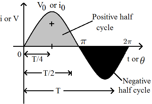
and $\text{V}=\text{V}_0\ \sin\omega\text{t}=\text{V}_0\ \sin2\pi\text{v t}=\text{V}_0\sin\frac{2\pi}{\text{T}}\text{t}$
where $i$ and $V$ are instantaneous values of current and voltage,
$i _0$ and $V _0$ are peak values of current and voltage
$\omega =$ Angular frequency in $\frac{\text{red}}{\text{sec}}, v =$ Frequency in $Hz$ and $T =$ time period
Accoeding to the problem, $f = 50Hz, I = 5A$
$\text{t}=\frac{\text{I}}{300}\text{s}$
$\text{I}_0=\text{Peak value}=\sqrt{2}(\text{I}_\text{rms})=5\sqrt{2}$
$=5\sqrt{2}\text{A}$
From, $\text{I}=\text{I}_0\sin\omega\text{t}=5\sqrt{2}\sin2\pi\text{vt}=5\sqrt{2}\sin2\pi\times50\times\frac{1}{300}$
$=5\sqrt{2}\sin\frac{\pi}{3}=5\sqrt{2}\times\frac{\sqrt{3}}{2}=5\sqrt{\frac{3}{2}}\text{A}$
View full question & answer→MCQ 551 Mark
In a series $LCR$ circuit, resonance occurring at $105 Hz$ . At that time, the potential difference across the $100$ resistance is $40 V$ while the potential difference across the pure inductor is $30 v$ . The inductance $L$ of the inductor is equal to.
- A
$2.0 \times 10^{-4}$
- B
$3.0 \times 10^{-4}$
- ✓
$1.2 \times 10^{-4}$
- D
$2.4 \times 10^{-4}$
AnswerCorrect option: C. $1.2 \times 10^{-4}$
In a series $LCR$ circuit, resonance occurring at $105 \ H$z . At that time, the potential difference across the $100$ resistance is $40 V$ while the potential difference
across the pure inductor is $30 V$ . The inductance $L$ of the inductor is equal to Current( $( i )=\frac{ V _{ r }}{ R }=\frac{100}{40}=2.5 A$
the inductor value is $V _{ L }= i \times( wL )$
$L =\frac{30}{2.5 \times 2 \times \pi 1 \times 105}=1.2 \times 10^{-4} H$
View full question & answer→MCQ 561 Mark
A $5\ cm$ long solenoid having $10 \ ohm$ resistance and $5mH$ inductance is joined to a $10V$ battery. At steady state, the current through the solenoid $($in ampere$)$ will be.
AnswerAt steady state inductor behave like short circuit.
$\text{i}=\frac{\text{v}}{\text{r}}=\frac{10}{10}=1\text{A}$
View full question & answer→MCQ 571 Mark
The magnetic field energy in an inductor changes from maximum value to minimum value in $5.0ms$ when connected to an $AC$ source. The frequency of the source:
- A
$20Hz.$
- ✓
$50Hz$.
- C
$200Hz.$
- D
$500Hz.$
AnswerCorrect option: B. $50Hz$.
Frequency of the source is remain constant $= 50Hz.$
View full question & answer→MCQ 581 Mark
Inductive reactance of a coil is expressed in.
AnswerInductive reactance or capacitive reactance are the impedance of an $AC$ circuit which has the units of ohms.
View full question & answer→MCQ 591 Mark
An $\text{LCR}$ series circuit with $100\Omega$ resistance is connected to an ac source of $200V$ and of frequency of $\frac{300 \text{rad}}{\text{s}}$. When only the capacitance is removed, the current lags behind the voltage by $600$. When only the inductance is removed, the current leads the voltage by $60^\circ $ the current through the circuit is:
AnswerSince current lead and lag are same So, circuit is in resonance, so, circuit is purely resistive circuit.
So, $\text{i}=\frac{\text{V}}{\text{R}}$
$=\frac{200}{100}$
$=2\text{A}$
View full question & answer→MCQ 601 Mark
A capacitor acts as an infinite resistance for.
- ✓
$DC$
- B
$AC$
- C
$DC$ as well as $AC$
- D
neither $AC$ nor $DC$
AnswerCapacitors contain at least two electrical conductors separated by a dielectric/ insulator and is used to store energy electrostatically between the conductors. It acts like an open circuit and hence acts like an infinite resistance for $DC$ currents.
View full question & answer→MCQ 611 Mark
In the given figure as shown, the reading of the ammeter in ampere is.
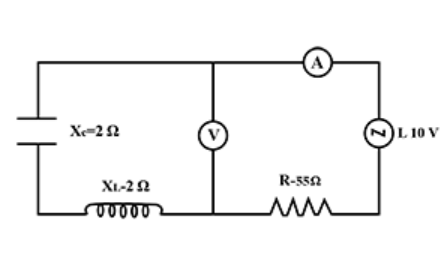
Answer$\text{I}=\frac{\text{E}}{\sqrt{\text{R}^2+(\text{X}_\text{L}-\text{X}_\text{C})^2}}$
$=\frac{110}{\sqrt{55^2+(2-2)^2}}$
$=\frac{110}{55}=2\text{A}$
View full question & answer→MCQ 621 Mark
An inductor coil of some resistance is connected to an AC source. Which of the following quantities have zero average value over a cycle?
- A
- B
Induced emf in the inductor.
- C
- ✓
AnswerExplanation:
$\text{I}=\text{I}_0\sin\omega\text{t}$
Average value of current over a cycle = 0
$\text{V}=\text{V}_0\cos\omega\text{t}$
$=\text{V}_0\sin\bigg(\omega\text{t}+{\frac{\pi}{2}}\bigg)$
Average value of induced emf in inductor over a cycle = 0. View full question & answer→MCQ 631 Mark
In a series $\text{L - C - R}$ circuit, current in the circuit is $11A$ when the applied voltage is $220V$. Voltage across the capacitor is $200V$. If value of resistor $20\Omega$ then the voltage across the unknown inductor is.
AnswerCorrect option: B. $200V$
The given $\text{LCR}$ circuit is in resonance. Inductive reactance magnitude $\text{XL}$ increases as frequency increases while capacitive reactance magnitude $\text{XC}$ decreases with the increase in frequency.
At one particular frequency, these two reactances are equal in magnitude but opposite in sign; that frequency is called the resonant frequency fO for the given circuit. Hence, at resonance:
$\text{XL = XC}$
So the voltage across rthe unknown inductor is $200V$ as same as the voltage across the capacitor.
View full question & answer→MCQ 641 Mark
An $\text{LCR}$ circuit has L = 10 mH, $\text{R}=3\Omega$ and $\text{C}=1\mu\text{ F}$ connected in series to a source of $15\cos\omega\text{t}$ volt. The current amplitude at a frequency that is $10\%$ lower than the resonant frequency is:
- A
$0.5A$
- ✓
$0.7A$
- C
$0.9A$
- D
$1.1A$
AnswerCorrect option: B. $0.7A$
Resonant frequency, $\text{w}_\text{o}=\frac{1}{\sqrt{\text{LC}}}=\frac{1}{\sqrt{(10\times10^{-3})(10^{-6})}}=\frac{10^4\text{rad}}{\text{s}}$
New frequency $\omega=(0.9)\omega_\text{o}=9\times\frac{10^3\text{rad}}{\text{s}}$
We have new $\text{X}_\text{L}=\omega\text{L}=9\times10^3\times10\times10^{-3}=90\Omega\text{ and}\text{ X}_\text{C}=\frac{1}{\omega\text{C}}=111.11\text{ohm.}$
Thus we calculate new $Z$ as
$\sqrt{3^2+[90-111.11]^2}$
$=21.32\Omega$
Current amplitude $=\frac{\text{V}_\text{o}}{\text{Z}}=\frac{15}{21.32}=0.7\text{A}$
View full question & answer→MCQ 651 Mark
The capacitance in an oscillatory $LC$ circuit is increased by $1\%$. The change in inductance required to restore its frequency of oscillation is to.
- A
decrease it by $0.5\%$
- B
increase it by $1\%$
- ✓
decrease it by $1\%$
- D
decrease it by $2\%$
AnswerCorrect option: C. decrease it by $1\%$
View full question & answer→MCQ 661 Mark
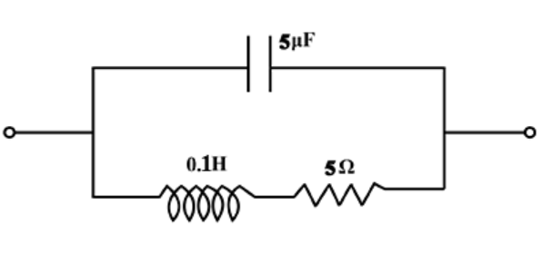
In the circuit shown in fig., the resonant frequency is.
- A
$200Hz$
- B
$220Hz$
- ✓
$225.08Hz$
- D
$230Hz$
AnswerCorrect option: C. $225.08Hz$
The resonant frequecy of a circuit is given by $\text{f}=\frac{1}{2\pi\sqrt{\text{LC}}}$
Given $\text{L}=0.1\text{H }\text{C}=5\mu\text{F }\text{R}=5\Omega$
Substituting them in formula for $f$ gives
$f = 225.08 Hz.$
View full question & answer→MCQ 671 Mark
At low frequency a condenser offers:
- ✓
- B
- C
- D
impedance of condenser is independent of frequency
Answer$\text{Z}=\frac{1}{\text{WC}}$
$\text{W}\downarrow\text{Z}\uparrow$
View full question & answer→MCQ 681 Mark
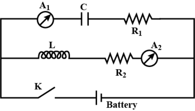
In a circuit inductance $L$ and capacitance $C$ are connected as shown in figure. $A_1$ and $A_2$ are ammeters. When key $K$ is pressed to complete the circuit, then just after closing key $(K)$, the readings of $A_1$ and $A_2$ will be.
- A
zero in both $A_1$ and $A_2$
- B
maximum in both $A_1$ and $A_2$
- C
zero in $A _1$ and maximum in $A _2$
- ✓
maximum in $A _1$ and zero in $A _2$
AnswerCorrect option: D. maximum in $A _1$ and zero in $A _2$
Initially there is no $D.C$ current in inductive circuit and maximum $D.C$ current is in capacitive current. Hence, the current is zero in $A _2$ and maximum in $A _1$
View full question & answer→MCQ 691 Mark
An $A.C.$ circuit containing only capacitance, the current:
- A
Lags the voltage by $90^\circ $
- ✓
Leads the voltage by $90^\circ $
- C
Remains in phase with voltage
- D
Lags the voltage by $180^\circ $
AnswerCorrect option: B. Leads the voltage by $90^\circ $
In an $a.c.$ circuit containing resistance onIy voltage $\ $ current remain in the same phase. If circuit contains inductance only, voltage remains ahead of current by phase difference of $90^\circ $. If circuit contains capacitance only, current remains ahead of voltage by a phase difference of $90^\circ .$
View full question & answer→MCQ 701 Mark
The square root of the product of inductance and capacitance has dimensions of.
Answer$\text{f}=\frac{1}{\sqrt{\text{LC}}}$
$\text{or}{\sqrt{\text{LC}}}=\text{T}$
View full question & answer→MCQ 711 Mark
An a.c. supply of $100$ volts is applied to a capacitor of capacitance $20 \mu F$. If the current in the circuit is $0.628$ A, the frequency of $a.c.$ must be.
- ✓
$50 \ Hz$
- B
$60 \ Hz$
- C
$25 \ Hz$
- D
$40 \ Hz$
AnswerCorrect option: A. $50 \ Hz$
$\text{Y}=100\text{V, C}=2\mu\text{F}=20\times10^{-6}$
$\text{I}=0.628\text{A,v}=?$
$\text{X}_\text{C}=\frac{\text{V}}{\text{I}}=\frac{100}{0.628}$
$\Rightarrow\frac{1}{2\pi\text{vC}}=\frac{100}{0.628}$
$\text{v}=\frac{0.628}{100\times2\pi\text{C}}$
$=50\text{ Hz}$
View full question & answer→MCQ 721 Mark
If we increase the driving frequency in a circuit with a purely resistive load, then amplitude $VR.$
AnswerWe know that $VR$ does not depend on driving frequency in a purely resistive circuit. So, If we increase the driving frequency in a circuit with a purely resistive load, then amplitude remain in the same.
View full question & answer→MCQ 731 Mark
What is the value of inductance $L$ for which the current is a maximum in a series $\text{LCR}$ circuit with $\text{C}=10\mu\text{F}$ and $\omega=1000_\text{s}^{-1}$?
AnswerCorrect option: B. $100mH$
View full question & answer→MCQ 741 Mark
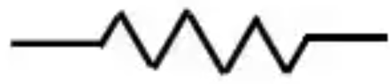
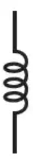
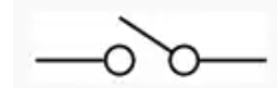
Symbol of Inductance in electric circuit is-
Answer$A$ is for resitance, $B$ is for inductance, $C$ is for a switch and $D$ is for Galvanometer.
View full question & answer→MCQ 751 Mark
A resistor and a capacitor are in series across a $20V$ ac source. Circuit impedance is $4.33\text{k}\Omega$ Current flow in the circuit is.
- A
$9.2mA$
- B
$92mA$
- ✓
$4.6mA$
- D
$460mA$
AnswerCorrect option: C. $4.6mA$
Voltage of the source $V = 20$ volts
$\text{Z}=4.33\text{k}\Omega=4.33\times10^3\Omega$
Thus current in the circuit $\text{I}=\frac{\text{V}}{\text{Z}}$
$\therefore\text{I}=\frac{20}{4.33\times10^3}=4.6\times10^{-3}\text{A}$
$\Rightarrow\text{I}=4.6\text{mA}$
View full question & answer→MCQ 761 Mark
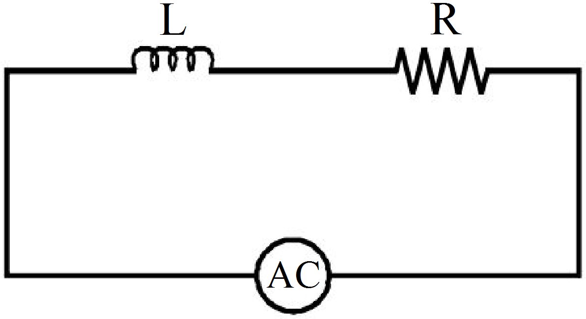
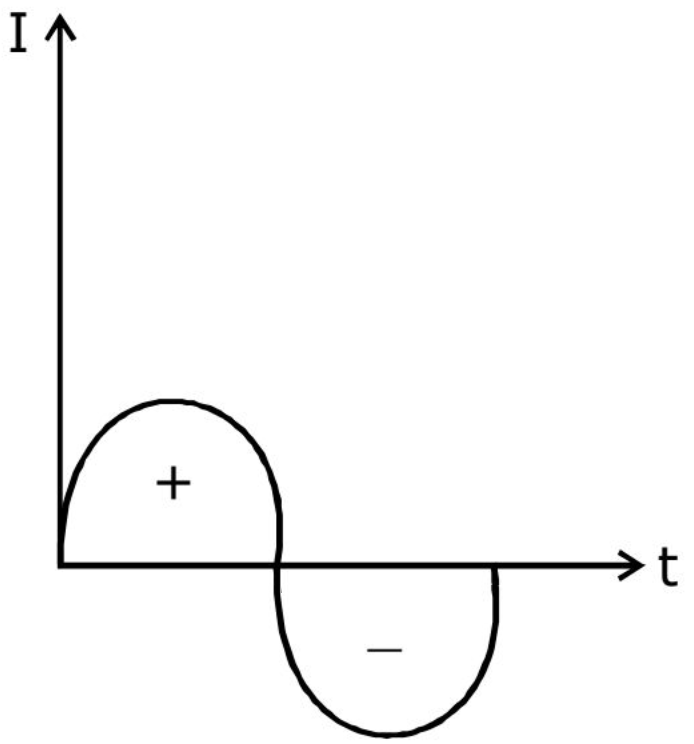
A mixer of $100\Omega$ resistance is connected to an $A.C.$ source of $200V$ and $50$ cycles $/\sec$. The value of average potential difference across the mixer will be:
- A
$308 V$
- B
$264 V$
- C
$220 V$
- ✓
AnswerWe need to find the average potential difference across the mixer. Here by average we mean average over a long period of time. As we know in one complete cycle, average voltage across the mixer is zero. $($In one complete cycle current changes the direction and net voltage across a resistor is zero$).$
So when in one complete cycle voltage drop across the resistor is zero, then the average voltage drop across the resistor $($mixer$)$ is zero.
View full question & answer→MCQ 771 Mark
An inductor, a resistor and a capacitor are joined in series with an $AC$ source. As the frequency of the source is slightly increased from a very low value, the reactance.
- ✓
of the inductor increases
- B
of the resistor increases
- C
of the capacitor increases
- D
AnswerCorrect option: A. of the inductor increases
View full question & answer→MCQ 781 Mark
For an $\text{LCR}$ circuit, the power transferred from the driving source to the driven oscillator is $\text{P}=\text{FZ}\cos\phi$.
- A
Here, the power factor $\cos\phi\geq0,\text{P}\geq0$.
- B
The driving force can give no energy to the oscillator $(P = 0)$ in some cases.
- C
The driving force cannot syphon out $(P < 0)$ the energy out of oscillator.
- ✓
Answer
- Here, the power factor $\cos\phi\geq0,\text{P}\geq0$.
- The driving force can give no energy to the oscillator $(P = 0)$ in some cases.
- The driving force cannot syphon out $(P < 0)$ the energy out of oscillator.
Solution:
Key Concept: Power Factor.
- It may be defined as cosine of the angle of lag of lead $($i.e., $\cos\phi).$
- It is also defined as the radio of resistance and impedange $\Big(\text{i.e.,} \frac{\text{R}}{\text{Z}}\Big)$.
- $\text{The radio}=\frac{\text{True power}}{\text{Apparent power}}=\frac{\text{W}}{\text{VA}}=\frac{\text{kW}}{\text{kVA}}=\cos\phi$
In the given problem power transferred,
$\text{P}=\text{I}^2\text{Z}\cos\phi$
where I is the current, $Z =$ Impedance and $\cos\phi$ is power factor
- As power factor, $\cos\phi=\frac{\text{R}}{\text{Z}}$
where $R > 0$ and $Z > 0$
$\Rightarrow\ \cos\phi>0\Rightarrow\ \text{P}>0$
- When $\phi=\frac{\pi}{2} ($in case of $L $ of $C), P = 0.$
- From $(a)$, it is clear that $P < 0$ is not possible.
View full question & answer→MCQ 791 Mark
The equation of an alternating voltage is $E = 220 E = 220$.Then the impedance of the circuit is:
- A
$10$ ohm
- ✓
$22$ ohm
- C
$11$ ohm
- D
$17$ ohm
AnswerCorrect option: B. $22$ ohm
Our experts are building a solution for this.
View full question & answer→MCQ 801 Mark
A series $AC$ circuit has a resistance of $4\Omega$ and a reactance of $3\Omega$. The impedance of the circuit is.
- ✓
$5\Omega$
- B
$7\Omega$
- C
$\frac{12}{7\Omega}$
- D
$\frac{7}{12\Omega}$
AnswerCorrect option: A. $5\Omega$
Impedance$(Z) =\sqrt{\text{R}^2+\text{X}^2}$
where, $R =$ resistance
$X =$ reactance
Given $\text{R}=4\Omega\text{ and }\text{X}=3\Omega$
Substitute values back in equation
$\text{Z}=\sqrt{4^2+3^2}$
$\text{Z}=5\Omega$
View full question & answer→MCQ 811 Mark
In non-resonant circuit, what will be the nature of the circuit for frequencies higher than the resonant frequency?
AnswerAt resonant frequency
$\text{X}_\text{L}=\text{X}_\text{C}=\Big(\omega\text{L}=\frac{1}{\omega\text{C}}\Big)$
At frequencies higher than resonance frequencies
$\text{X}_\text{L}>\text{X}_\text{C}$
i.e., behaviour is inductive.
View full question & answer→MCQ 821 Mark
An AC source producing emf $\in=\in_{0}\Big[\cos\big(100\pi\text{s}^{-1}\big)\text{t}+\cos\big(500\pi\text{s}^{-1}\big)\text{t}\Big]$ is connected in series with a capacitor and a resistor. The steady-state current in the circuit is found to be $\text{i}=\text{i}_1\cos\Big[\big(100\pi\text{s}^{-1}\big)\text{t}+\phi_1\Big]+\text{i}_2\cos\Big[\big(500\pi\text{s}^{-1}\big)\text{t}+\phi_2\Big].$
AnswerCorrect option: C. $i_1 < i_2$
$\text{Q}=\text{C}\in=\in_{0}\text{C}\Big[\cos\big(100\pi\text{s}^{-1}\big)\text{t}+\cos\big(500\pi\text{s}^{-1}\big)\text{t}\Big]$
$\text{i}=\frac{\text{dQ}}{\text{dt}}$
$\text{Q}=\text{C}\in=\in_{0}\text{C}\Big[\cos\big(100\pi\text{s}^{-1}\big)\text{t}+\cos\big(500\pi\text{s}^{-1}\big)\text{t}\Big]$
$\in_0\text{C}\times100\pi\Big[\sin\big(100\pi\text{s}^{-1}\big)\text{t}\Big]\\+\in_0\text{C}\times500\pi\Big[\sin\big(500\pi\text{s}^{-1}\big)\text{t}\Big]$
$=100\text{C}\pi\in_0\cos\Big[\big(100\pi\text{s}^{-1}\big)\text{t}+\phi_1\Big]\\+500\text{C}\pi\in_0\cos\Big[\big(500\pi\text{s}^{-1}\big)\text{t}+\phi_2\Big]$
$\text{i}_1=100\pi\in_0\text{C}$ and $\text{i}_2=500\pi\in_0\text{C}$
$\text{i}_2>\text{i}_1$
View full question & answer→MCQ 831 Mark
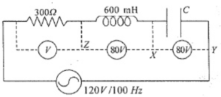
In above circuit, what is the potential drop across $ZY?$
- A
$160 V$
- B
$80\sqrt{80}$
- C
$80 V$
- ✓
View full question & answer→MCQ 841 Mark
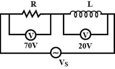
The adjoining figure shows an $AC$ circuit with resistance $R$, inductance $L$ and source voltage $Vs$. Then.
- ✓
the source voltage $V _{ s }=72.8 V$
- B
the phase angle between current and source voltage is $\tan-\frac{7}{2}$
- C
Both $(a)$ and $(b)$ are correct.
- D
Both $(a)$ and $(b)$ are wrong.
AnswerCorrect option: A. the source voltage $V _{ s }=72.8 V$
a. the source voltage $V _5=72.8 V$.
View full question & answer→MCQ 851 Mark
In the $AC$ network shown in figure, the rms current flowing through the inductor and capacitor are $0.6A$ and $0.8A$ respectively. Then the current coming out of the source is
AnswerCorrect option: C. $0.2A$
$IC$ is $90^{\circ}$ ahead of the applied voltage and $I_L$ lags behind the applied voltage by $90^{\circ}$.
So, there is a phase difference of $180^{\circ}$ between $IL$ and $IC$
$\therefore I=I_C-I_L=0.2 A$
View full question & answer→MCQ 861 Mark
The unit of susceptance is.
AnswerCorrect option: B. $\text{ohm}^{-1}$
Susceptance is the imaginary part of admittance.
The admittance is the inverse of impedance.
Unit of admittance is ohm. Unit of admittance is ohm$^{-1}$ or siemens.
Unit of susceptance is same as of admittance.
View full question & answer→MCQ 871 Mark
In the following diagram, the value of emf of $A.C.$ source will be:
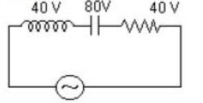
AnswerCorrect option: B. $40\sqrt{2}\text{V}$
$\text{E}_\text{rms}=\sqrt{\text{V}^2_\text{R}+(\text{V}_\text{L}-\text{V}_\text{c})^2}$
$=\sqrt{40^2+(40-80)^2}$
$=\sqrt{40^2+40^2}$
$=40\sqrt{2}\text{V}$
View full question & answer→MCQ 881 Mark
If the values of $L, C$ and $R$ in a series $\text{L - C - R}$ circuit are $100\text{mH},100\mu\text{F}$ and $100\Omega$ respectively then the value of resonant frequency will be.
AnswerCorrect option: A. $\frac{10}{2\pi}\text{Hz}$
Resonant frequency $=\frac{1}{2\pi\sqrt{\text{LC}}}$
$=\frac{1}{2\pi\sqrt{10^{-6}}}$
$=\frac{10}{2\pi}\text{Hz}$
View full question & answer→MCQ 891 Mark
If in a series $L-C$ - $R$ ac circuit, the voltages across $L, C$ and $R$ are $V_1, V_2$ and $V_3$ respectively, then the voltage of the source is always.
AnswerCorrect option: D. none of the above is true
The voltages across different elements in $A C$ circuit add vectorially.
The voltages across inductor and capacitor are out of phase and at $90^{\circ}$ to that across resistor.
Hence net voltage across source $=\sqrt{\left( V _1- V _2\right)+ V _3^2}$.
View full question & answer→MCQ 901 Mark
A coil of self$-$inductance $L$ is connected in series with a bulb $B$ and an $AC$ source. Brightness of the bulb decreases when.
AnswerCorrect option: D. An iron rod is inserted in the coil
As the iron rod is inserted, the magnetic field inside the coil magnetizes the iron increasing the magnetic field inside it. Hence. the inductance of the coil increases. Consequently, the inductive reactance of the coil increases. As a result, a larger fraction of the applied $AC$ voltage appears across the lnductor, leaving less voltage across the bulb.Therefore' the brightness of the light bulb decreases.
View full question & answer→MCQ 911 Mark
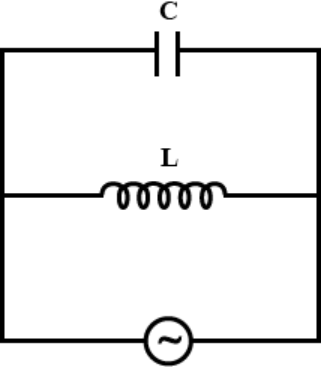
The circuit shown in Fig. acts as a.
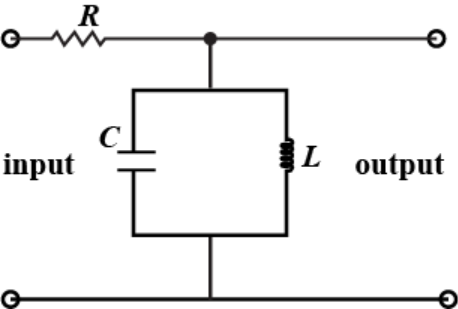
AnswerThe circuit shown in figure has capacitor and inductor in parallel so their will be current flowing continuously with energy being transformed into electrical in capacitor and magnetic in inductor, hence it is a tuned filter.
View full question & answer→MCQ 921 Mark
A coil of $10\text{mH}$ and $10\Omega$ resistance is connected in parallel to a capacitance of $0.1\mu\text{F}$ The impedance of the.
- A
$10^2\Omega$
- ✓
$10^4\Omega$
- C
$10^6\Omega$
- D
$10^8\Omega$
AnswerCorrect option: B. $10^4\Omega$
View full question & answer→MCQ 931 Mark
A solenoid of length $10\ cm$, diameter $1\ cm,$ number of turns $500$ with relative permeability of the core $2000$, is connected to an ac source of frequency $50\ Hz$. Then, the reactance is.
- A
$\text{Zero}$
- B
$55\Omega$
- C
$105\Omega$
- ✓
$155\Omega$
AnswerCorrect option: D. $155\Omega$
Inductance of the solenoid $=\text{L}=\frac{\mu\text{N}^2\text{A}}{1}=0.493\text{H}$
reactance of this solenoid $=\text{L}\omega=\text{L}2\pi\text{f}=155\Omega$
View full question & answer→MCQ 941 Mark
When the rms voltages $V_L, V_C$ and $V_R$ are measured respectively across the inductor $L$, the capacitor $C$ and the resistor $R$ in a series $\text{L C R}$ circuit connected to an $A C$ source, it is found that the ratio $V_L: V_C: V_R=1: 2: 3$. If the rms voltage of the $AC$ source is $100 V$ , then $V _{ R }$ is close to:
- A
$50V$
- B
$70V$
- ✓
$90V$
- D
$100V$
View full question & answer→MCQ 951 Mark
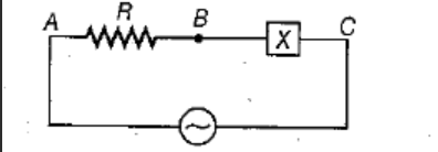
In the given circuit $R$ in pure resistance and $X$ is unknown circuit element. $A n A C$ voltage source is applied across $A$ and $C$. If $V_{A B}=V_{A C}$, then $X$ is.
- A
- B
- ✓
Combination of inductance and capacitance at resonance
- D
AnswerCorrect option: C. Combination of inductance and capacitance at resonance
Since the voltage across the resistive element is same as the voltage applied, the voltage drop across $BC$ is zero. This is possible only when the ohmic value of the element connected across $BC$ is zero. So, $X$ should be combination of inductance and capacitance at resonance.
View full question & answer→MCQ 961 Mark
A sinusoidal voltage $\text{V}=200\sin314\text{t}$ is applied to a $10\Omega$ resistor. Find the peak voltage.
- ✓
$200V$
- B
$400V$
- C
$600V$
- D
$800V$
AnswerCorrect option: A. $200V$
General sinusoidal voltage variation is given by:
$\text{V}=\text{V}_0\sin(\omega\text{t})$
Here, in this equation $V_0$ is peak voltage.
So, on comparing both equation we get:
$\text{V}_0=200\text{V},\omega=314$
View full question & answer→MCQ 971 Mark
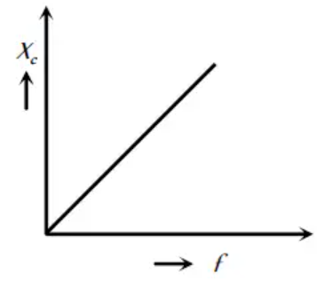
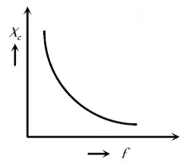
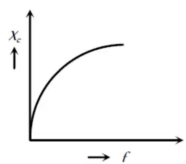
The correct curve representing the variation of capacitive reactance $X_c$ with frequency f is.
AnswerC. 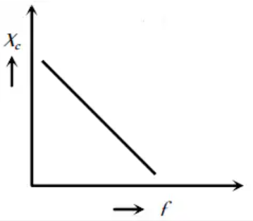 Explanation:
$\text{X}_\text{C}=\frac{1}{\text{C}2\pi\text{f}}$
$X_c$ and f are inversely proportional. View full question & answer→MCQ 981 Mark
In the following circuit the values of $L , C , R$ and $E 0$ are $0.01 H , 10^{-5} F, 25 \Omega$ and $220$ volt respectively. The value of current flowing in the circuit at $f =0$ and $f =\infty$ will respectively be.
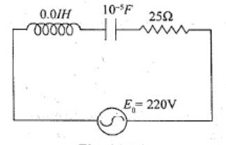
- A
$8 A$ and $0 A$
- ✓
$0 A$ and $0 A$
- C
$8 A$ and $8 A$
- D
$0 A$ and $8 A$
AnswerCorrect option: B. $0 A$ and $0 A$
$\text{I}=\frac{220}{25+\text{j}\Big(0.1\times2\pi\text{f }-\frac{1}{10^{-5}2\pi\text{f}}\Big)}$
$\text{I}=0\text{ at }\text{f}=0$
$\text{I}=0\text{ at }\text{f}=\infty$
View full question & answer→MCQ 991 Mark
In an $LCR$ circuit as shown below both switches are open initially. Now switch $S_1$ is closed, $S_2$ kept open. $( q$ is charge on the capacitor and $\tau= RC$ is capacitive time constant$)$. Which of the following statement is correct?
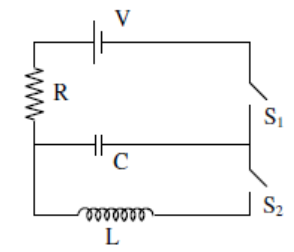
- A
$\text{At t}=\tau,\text{q}=\frac{\text{CV}}{2}$
- ✓
$\text{At t}=2\tau,\text{q}={\text{CV}}(1-\text{e}^{-2})$
- C
$\text{At t}=\frac{\text{T}}{2},\text{q}={\text{CV}}(1-\text{e}^{-1})$
- D
Work done by the battery is half of the energy dissipated in the resistor.
AnswerCorrect option: B. $\text{At t}=2\tau,\text{q}={\text{CV}}(1-\text{e}^{-2})$
Charge on the capacitor at any time $`t'$ is
$\text{q}=\text{CV}(1-\text{e}\frac{-\text{t}}{\tau})$
$\text{at }\text{t}=2\tau$
$\text{q}=\text{CV}(1-\text{e}^{-2})$
View full question & answer→MCQ 1001 Mark
A $6kHz$ sinusoidal voltage is applied to a series $RC$ circuit. The frequency of the voltage across the resistor is.
- A
$0Hz$
- B
$12kHz$
- ✓
$6kHz$
- D
$18kHz$
AnswerCorrect option: C. $6kHz$
Frequency of applied voltage and voltage or current accross any component are same. As we know,
$\text{I}=\frac{\text{V}}{\text{Z}}$ and $Z$ has nothing to do with frequency
$\Rightarrow \text{IandV}$ have same frequency.
And also according to $KVL V = V _1+ V _2+ V _3$
$\Rightarrow $ voltage and current across any component have same frequency i.e $6kHz.$
View full question & answer→