Questions

5 Marks Questions

Take a timed test

6 questions · self-marked practice — reveal the answer and mark yourself.

Question 15 Marks
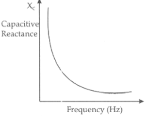
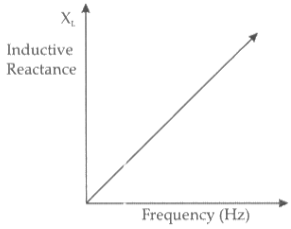
$a$. Draw graphs showing the variations of inductive reactance and capacitive reactance with the frequency of the applied ac source.
$b$. Draw the phasor diagram for a series $RC$ circuit connected to an ac source.
$c$. An alternating voltage of $220 V$ is applied across a device $X,$ a current of $0.25$ A flows, which lag behind the applied voltage in phase by $\frac{\pi}{2}$ radian. If the same voltage is applied across another device $Y,$ the same current flows but now it is in phase with the applied voltage.
$i$. Name the devices $X$ and $Y$.
$ii$. Calculate the current flowing in the circuit when the same voltage is applied across the series combination of $X$ and $Y$.
Answer
$a$. Drawing the two graphs the graph shows the variation of capacitive resistance with frequency and inductive resistance with frequency.
The two graphs are as shown
Image

Image
$b$. Drawing the phaser diagram
$($the current leads the voltage by an angle $\theta$ where $0<\theta<\frac{\pi}{2} )$.
The required phaser diagram is as shown.
Image
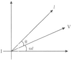
$[$Here, $\theta=\tan ^{-1}\left[\frac{1}{\omega C R}\right]$
$c.i$. In device $X$ :
Current lags behind the voltage by $\frac{\pi}{2}$
$\therefore X$ is an inductor.
In device $Y$ :
Current in phase with the applied voltage.
$\therefore Y$ is resistor.
$ii$. We are given that
$0.25=\frac{2 n 0}{X_L}$
or $ X _{ L }=\frac{2 n 0}{02} \Omega=880 \Omega$
Also $0.25=\frac{220}{X_R}$
$\therefore X_R=\frac{220}{0.25} \Omega=880 \Omega$
For the series combination of $X$ and $Y,$
Equivalent impedance $=\sqrt{X_L^2+X_R^2}=(880 \sqrt{2}) \Omega$
$\therefore $ Current flowing $ \frac{220}{880 \sqrt{2}} A=0.177 A$
View full question & answer
Question 25 Marks
Two parallel metal plates P and Q are inserted at equal distances into a plane capacitor as shown in fig. Plates A and B of the capacitor are connected to a battery of e.m.f. V.
a. What are the potentials of the four plates?
Image
a. What are the potentials of the four plates?
b. How will the potentials of plates P and Q and the intensities of the fields in each of the three spaces change after plates P and Q have been connected by a wire?
c..What will happen to the charges on plates A and B, when plates P and Q are connected with a wire?
d. Will there be charges on the plates P and Q after connecting them with a wire?
Answer
a. The plates P and Q divide the space between the plates A and B in three equal parts. Since V = Ed, the potentials of the plates A, P, Q, and B will be respectively V, 2V/3, V/3 and 0.
b. When the plates P and Q are connected with a wire, the space between the plates A and B gets divided into two equal parts. Hence, the potentials of plates A, P, Q, and B will be respectively V, V/2, V/2 and 0.
Since the potential difference between the plates A and P; and between the plates, Q and B have increased from V/3 to V/2, the electric field between these plates will increase. As the potential difference the plates P and Q is zero, the electric field will also be zero.
c. Since the potential difference between the plates A and P and between the plates Q and B have increased, the charge on the plates A and B will increase.
d. Yes, the plate P will have a positive charge and the plate Q will have a negative charge.

View full question & answer
Question 35 Marks
Two charged conducting spheres of radii a and b are connected to each other by a wire. What is the ratio of electric fields at the surfaces of the two spheres? Use the result obtained to explain why charge density on the sharp and pointed ends of a conductor is higher than on its flatter portions.
Answer
Suppose that two connected conducting spheres of radii a and b possess charges $q_1$ and $q_2$ respectively.
On the surface of the two spheres, the potential will be
$V_1=\frac{1}{4 \pi \varepsilon_0} \cdot \frac{q_1}{a}$
$V_2=\frac{1}{4 \pi \varepsilon_0} \cdot \frac{q_2}{b}$
Till the potentials of two conductors become equal, the flow of charges continues.
Thus $,V _1= V _2$
$\frac{1}{4 \pi \varepsilon_0} \cdot \frac{q_1}{a}$
$=\frac{1}{4 \pi \varepsilon_0} \cdot \frac{q_2}{b}$
$\frac{q_1}{q_2}=\frac{a}{b}$
Now, the electric field on the two spheres is given as
$E_1=\frac{1}{4 \pi \varepsilon_0} \cdot \frac{q_1}{a^2}$
$E_2=\frac{1}{4 \pi \varepsilon_0} \cdot \frac{q_2}{b^2}$
$\text { or } \frac{E_1}{E_2}=\frac{q_1}{q_2} \cdot \frac{b^2}{a^2}$
$=\frac{a}{b} \cdot \frac{b^2}{a^2}=\frac{b}{a}$
Therefore $, b$ : a is the ratio of the electric field of the first sphere to that of the second sphere.
The surface charge densities of the two spheres are given as
$\sigma_1=\frac{q_1}{4 \pi a^2}$
$($As the charges are distributed uniformly over the surfaces of conducting spheres$)$
$\sigma_2=\frac{q_2}{4 \pi b^2}$
$\therefore \frac{\sigma_1}{\sigma_2}=\frac{q_1}{q_2} \cdot \frac{b^2}{a^2}$
$=\frac{a}{b} \cdot \frac{b^2}{a^2}=\frac{b}{a}$
Therefore, the surface charge densities are inversely related with the radii of the sphere.
The surface charge density on the sharp and pointed ends of a conductor is higher than on its flatter portion
since a flat portion may be taken as a spherical surface of large radius and a pointed portion as that of small radius.
View full question & answer
Question 45 Marks
$i$. An alternating voltage $V = V _{ m } \sin \omega t$ applied to a series $\text{L - C - R}$ circuit derives a current given by $I = I _{ m } \sin \ (\omega t+\phi)$. Deduce an expression for the average power dissipated over a cycle.
$ii$. For circuit used for transporting electric power, a low power factor implies large power loss in transmission. Explain.
Answer
$i$. Let at any instant, the current and voltage in an $\text{L - C - R}$ series $AC$ circuit is given by
$V=V_m \sin \omega t $ and 
$I=I_m \sin (\omega t+\phi)$
where $V _{ m }$ and $I _{ m }$ are the peak values of the $ac$ voltage and $ac $ current respectively.
The instantaneous power is given by
$P=V I=I_m \sin (\omega t+\phi) V_m \sin \omega t$
$\Rightarrow P=\frac{V_m I_m}{2}[2 \sin \omega t \sin (\omega t+\phi)]$
$\therefore P=V I=\frac{V_m I_m}{2}[\cos \phi-\cos (2 \omega t+\phi)] \ldots(i)$
$[\because 2 \sin A \sin B=\cos (A-B)-\cos (A+B)]$
Work done for a very small time interval dt is given by
$d W=P d t$
$\Rightarrow d W=V I d t$
$\therefore$ Total work done over a complete cycle i.e. from $0$ to $T$ is given by,
$W=\int_0^T V I d t$
$\text { But } P_{a v}=\frac{W}{T}=\frac{\int_0^T V I d t}{T}$
$\Rightarrow P_{a v}=\frac{1}{T} \int_0^T V I d t$
$=\frac{1}{T} \int_0^T \frac{V_m I_m}{2}[\cos \phi-\cos (2 \omega t+\phi)] d t$
$=\frac{V_m I_m}{2 T}\left[\int_0^T \cos \phi d t-\int_0^T \cos (2 \omega t+\phi) d t\right]$
$=\frac{V_m I_m}{2 T}[\cos \phi(t)]_0^T-0 \ ($By trigonometry$)$
$=\frac{V_m I_m}{2 T} \cos \phi \times T=\frac{V_m I_m}{2} \cos \phi$
$=\frac{V_m}{\sqrt{2}} \times \frac{I_m}{\sqrt{2}} \cos \phi$
$\Rightarrow P_{a v}=V_{r m s} I_{r m s} \cos \phi$
This is the required expression.
ii. Power factor, $\cos \phi=\frac{R}{Z}$
where, $R =$ resistance and $Z =$ impedance of the circuit.
Low power factor $( \cos \phi )$ implies lower ohmic resistance which implies larger power loss in power system $($transmission line$),$ because in power system power, $P \propto \frac{1}{R}$.
View full question & answer
Question 55 Marks
$i$. Using Huygens's construction of secondary wavelets explains how a diffraction pattern is obtained on a screen due to a narrow slit on which a monochromatic beam of light is incident normally.
$ii$. Show that the angular width of first diffraction fringe is half that of the central fringe.
$iii$. Explain why the maxima at $\theta=\left(n+\frac{1}{2}\right) \frac{\lambda}{a}$ a become weaker and weaker with increasing $n$.
Answer
$i$. We can regard the total contributions of the wavefront $LN$ at some point $P$ on the screen, as the resultant effect of the superposition of its wavelets like $LM , MM _2, M _2 N$.
These have to be superposed taking into account their proper phase differences.
Image

We, therefore, get maxima and minima,
i.e., a diffraction pattern, on the screen.
Maxima and minima are produced when the path difference between waves is a whole number of wavelengths or an odd number of half wavelengths respectively.
Conditions for first minima on the screen
$\operatorname{a \sin} \theta=\lambda$
$\Rightarrow \theta=\frac{\lambda}{a}$
$\operatorname{a \sin} \theta=\lambda$
$\Rightarrow \theta=\frac{\lambda}{a}$
$\therefore$ Angular width of the central fringe on the screen $($from the figure$)$
$=2 \theta=\frac{2 \lambda}{a}$
Angular width of first diffraction fringe $($From fig$)$
$=\frac{\lambda}{a}$
For the first diffraction, the angular width of the fringe is half that of the central fringe.
$iii$. Maxima becomes weaker and weaker with increasing $n$.
This is because the effective part of the wavefront, contributing to the maxima becomes smaller and smaller, with increasing $n$.
View full question & answer
Question 65 Marks
$i$. Draw a ray diagram showing the image formation by a compound microscope. Obtain the expression for total magnification when the image is formed at infinity.
$ii$. How does the resolving power of a compound microscope get affected, when
$1$. focal length of the objective is decreased.
$2$. the wavelength of light is increased ? Give reasons to justify your answer.
Answer
$i$. The ray diagram, showing image formation by a compound microscope, is given below ; $-$
Image
$ii.$ Linear Magnification due to objective lens is given by $=\frac{\tan \beta}{\tan \alpha}$
$\tan \beta=\frac{h^{\prime}}{L}=\frac{h}{f_o}$
$\frac{h^{\prime}}{h}=\frac{L}{f_0}$
$($where the distance between the second focal point of the objective and the first focal point of the eyepiece is called the tube length of the compound microscope and is denoted by $L)$
The eyepiece will act as a simple microscope, hence we may use the formula of magnification by a simple microscope for normal adjustment.
$m_e=\frac{D}{f_e}$
Total magnification, $m = m _{ o } \times m _{ e }$
$=\frac{L}{f_o} \times \frac{D}{f_e} d_{\min }$
$a$. From the equation, it is clear that resolving power increases when the focal length of the objective is decreased.
This is because the minimum separation, $d _{\min }$ decreases when f is decreased.
$b$. Resolving power decreases when the wavelength of light is increased.
​​​​​​​This is because the minimum separation, $d _{\text {min }}$ increases when $\lambda$ is increased.
View full question & answer