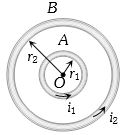
$A$ and $B$ are two concentric circular conductors of centre $O$ and carrying currents ${i_1}$ and ${i_2}$ as shown in the adjacent figure. If ratio of their radii is $1 : 2$ and ratio of the flux densities at $O$ due to $A$ and $B$ is $1 : 3$, then the value of ${i_1}/{i_2}$ is
Medium


Download our appand get started for free
Experience the future of education. Simply download our apps or reach out to us for more information. Let's shape the future of learning together!No signup needed.*
Similar Questions
- 1A charge $q$ moves in a region where electric field and magnetic field both exist, then force on it isView Solution
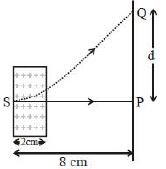
- 2An electron, moving along the $x-$ axis with an initial energy of $100\, eV$, enters a region of magnetic field $\vec B = (1.5\times10^{-3}T)\hat k$ at $S$ (See figure). The field extends between $x = 0$ and $x = 2\, cm$. The electron is detected at the point $Q$ on a screen placed $8\, cm$ away from the point $S$. The distance $d$ between $P$ and $Q$ (on the screen) is :......$cm$ (electron's charge $= 1.6\times10^{-19}\, C$, mass of electron $= 9.1\times10^{-31}\, kg$)View Solution
- 3To convert galvanometer into ammeter, shunt of $0.01\,\Omega $ is used. Resistance of galvanometer coil is $50\,\Omega $ and its maximum deflection current is $20\ mA$ . Range of ammeter isView Solution
- 4The magnetic moment of a bar magnet is $0.5 \mathrm{Am}^2$. It is suspended in a uniform magnetic field of $8 \times 10^{-2} \mathrm{~T}$. The work done in rotating it from its most stable to most unstable position is:View Solution
- 5A current of $0.1\, A$ circulates around a coil of $100$ $turns$ and having a radius equal to $5\, cm$. The magnetic field set up at the centre of the coil is $({\mu _0} = 4\pi \times {10^{ - 7}}\,weber/ampere - metre)$View Solution
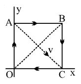
- 6$OABC$ is a current carrying square loop an electron is projected from the centre of loop along its diagonal $AC$ as shown. Unit vector in the direction of initial acceleration will beView Solution
- 7A thin wire of length $l$ is carrying a constant current. The wire is bent to form a circular coil. If radius of the coil, thus formed, is equal to $R$ and number of turns in it is equal to $n$, then which of the following graphs represent $(s)$ variation of magnetic field induction $(b)$ at centre of the coilView Solution
- 8The magnetic moment of a circular orbit of radius $‘r’$ carrying a charge $‘q’$ and rotating with velocity $v$ is given byView Solution
- 9An infinitely long wire, located on the $z$-axis, carries a current $/$ along the $+z$-direction and produces the magnetic field $\vec{B}$. The magnitude of the line integral $\int \vec{B} \cdot d l$ along a straight line from the point $(-\sqrt{3} a, a, 0)$ to $(a, a, 0)$ is given by [ $\mu_0$ is the magnetic permeability of free space.]View Solution
- 10One of the two identical conducing wires of length $L$ is bent in the form of a circular loop and the other one into a circular coil of $N$ identical turns. If the same current is passed in both, the ratio of the magnetic field at the central of the loop $(B_L)$ to that at the centre of the coil $(B_C),$; $.\,\frac {B_L}{B_C}$ will beView Solution