If resistance of the filament increases with temperature, what will be power dissipated in a $220\, V- 100\, W$ lamp when connected to $110\, V$ power supply
Easy
Download our app for free and get started
c
If resistance does not vary with temperature $P_{consumed} = $${\left( {\frac{{{V_A}}}{{{V_R}}}} \right)^2} \times {P_R} = {\left( {\frac{{110}}{{220}}} \right)^2} \times 100 = 25\,W$. But in second cases resistance decreases so consumed power will be more than $25\, W$
If resistance does not vary with temperature $P_{consumed} = $${\left( {\frac{{{V_A}}}{{{V_R}}}} \right)^2} \times {P_R} = {\left( {\frac{{110}}{{220}}} \right)^2} \times 100 = 25\,W$. But in second cases resistance decreases so consumed power will be more than $25\, W$

Download our appand get started for free
Experience the future of education. Simply download our apps or reach out to us for more information. Let's shape the future of learning together!No signup needed.*
Similar Questions
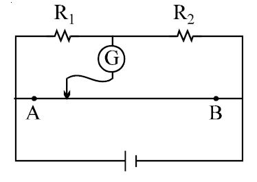
- 1In the figure shown for gives values of $R_1$ and $R_2$ the balance point for Jockey is at $40\,cm$ from $A$. When $R_2$ is shunted by a resistance of $10\, \Omega$ , balance shifts to $50\,cm.$ $R_1$ and $R_2$ are $(AB = 1 \,m)$View Solution
- 2A strip of copper and another of germanium are cooled from room temperature to $80\, K$. The resistance ofView Solution
- 3A source of $e.m.f.$ $E = 15\,V$ and having negligible internal resistance is connected to a variable resistance so that the current in the circuit increases with time as $i = 1.2 t + 3$. Then, the total charge that will flow in first five second will be ............... $C$View Solution
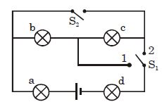
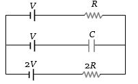
- 4Four lamps are connected in the way shown in the figure. When switch $S_2$ is open and switch $S_1$ is on position $-2$ , lamp $-b$ is the brightest, and lamp $-c$ and lamp $-d$ are the dimmest and are of the same brightness. Now $S_2$ is closed and $S_1$ is on position $-1$ , the sequence in brightness of the lamps is (with the first in the sequence being the brightest)View Solution
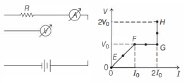
- 5In the circuit shown below (on the left) the resistance and the emf source are both variable. The graph of seven readings of the voltmeter and the ammeter ( $V$ and $I$, respectively) for different settings of resistance and the emf, taken at equal intervals of time $\Delta t$, are shown below (on the right) by the dots connected by the curve $E F G H$. Consider the internal resistance of the battery to be negligible and the voltmeter an ammeter to be ideal devices. (Take, $R_0 \equiv \frac{V_0}{I_0}$ ).View Solution
Then, the plot of the resistance as a function of time corresponding to the curve $E F G H$ is given by
- 6View SolutionIn the given circuit, with steady current, the potential drop across the capacitor must be
- 7A galvanometer together with an unknown resistance in series is connected to two identical batteries each of $1.5\, V$. When the batteries are connected in series, the galvanometer records a current of $1\,A$, and when batteries are in parallel the current is $0.6\,A$. What is the internal resistance of the battery ?View Solution
- 8The Kirchhooff's first law $\left(\sum i=0\right)$ and second law ( $\left.\sum i R=\sum E\right)$, where the symbols have their usual meanings, are respectively based onView Solution
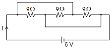
- 9The current $I$ flowing through the given circuit will be $.....A$.View Solution
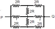
- 10The effective resistance between points $P$ and $Q$ of the electrical circuit shown in the figure isView Solution