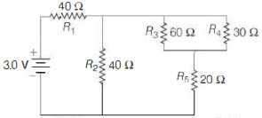
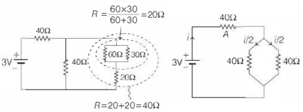
In the circuit shown below, the resistances are given (in $\Omega$ ) and the battery is assumed ideal with emf equal to $3.0 \,V$. The resistor that dissipates the most power is
KVPY 2011, Medium


Download our appand get started for free
Experience the future of education. Simply download our apps or reach out to us for more information. Let's shape the future of learning together!No signup needed.*
Similar Questions
- 1An electric bulb of $100\, watt$ is connected to a supply of electricity of $220\, V$. Resistance of the filament is ............. $\Omega$View Solution
- 2The resistance of a conductor at $15^{\circ} {C}$ is $16\, \Omega$ and at $100\, {C}$ is $20\, \Omega$. What will be the temperature coefficient of resistance of the conductor?View Solution
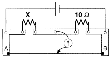
- 3A meter bridge is set-up as shown, to determine an unknown resistance ' $X$ ' using a standard $10$ ohm resistor. The galvanometer shows null point when tapping-key is at $52 \ cm$ mark. The end-corrections are $1 \ cm$ and $2 \ cm$ respectively for the ends $A$ and $B$. The determined value of ' $X$ ' isView Solution
- 4$1.6\, mA$ current is flowing in conducting wire then the number of electrons flowing per second isView Solution
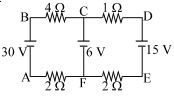
- 5The figure shows a network of four resistances and three batteries The current through the branch $CF$ is ............... $A$View Solution
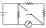
- 6In the circuit shown, the reading of the Ammeter is doubled after the switch is closed. Each resistor has a resistance $1\,\Omega$ and the ideal cell has an $e.m.f.$ $10\,V$. Then, the Ammeter has a coil resistance equal to ............ $\Omega$View Solution
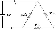
- 7View SolutionThe current in the adjoining circuit will be
- 8View SolutionIf an electric current is passed through a nerve of a man, then man
- 9The heat produced by a $100\, watt$ heater in $2$ minute will be equal toView Solution
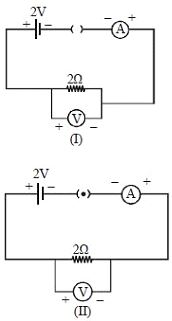
- 10For the circuits shown in figures $I$ and $II$, the voltmeter reading would beView Solution