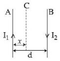
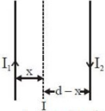
Two wires $A$ and $B$ are carrying currents $I_1$ and $I_2$ as shown in the figure. The separation between them is $d$. A third wire $C$ carrying a current $I$ is to be kept parallel to them at a distance $x$ from $A$ such that the net force acting on it is zero. The possible values of $x$ are
JEE MAIN 2019, Medium


Download our appand get started for free
Experience the future of education. Simply download our apps or reach out to us for more information. Let's shape the future of learning together!No signup needed.*
Similar Questions
- 1A thin circular wire carrying a current $I$ has a magnetic moment $M$. The shape of the wire is changed to a square and it carries the same current. It will have a magnetic momentView Solution
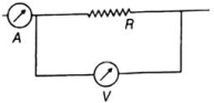
- 2In the adjoining circuit diagram, the readings of ammeter and voltmeter are $2\, A$ and $120 \,V$, respectively. If the value of $R$ is $75\, \Omega$, then the voltmeter resistance will be $\Omega$View Solution
- 3View SolutionThe motion of a charged particle can be used to distinguish between a magnetic field and electric field in a certain region by firing the charge
- 4A proton and a deutron ( $\mathrm{q}=+\mathrm{e}, m=2.0 \mathrm{u})$ having same kinetic energies enter a region of uniform magnetic field $\vec{B}$, moving perpendicular to $\vec{B}$. The ratio of the radius $r_d$ of deutron path to the radius $r_p$ of the proton path is:View Solution
- 5A conductor $ABCDE$, shaped as shown, carries a current i. It is placed in the $xy$ plane with the ends $A$ and $E$ on the $x$-axis. $A$ uniform magnetic field of magnitude $B$ exists in the region. The force acting on it will beView Solution
- 6A square shaped wire loop of mass $m$, resistance $R$ and side $a$ moving speed $v_{0}$, parallel to the $X$-axis, enters a region of uniform magnetic field $B$, which is perpendicular to the plane of the loop. The speed of the loop changes with distance $x(x < a)$ in the field, asView Solution
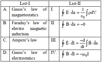
- 7Match List $I$ with List $II$View Solution
Choose the correct answer from the options given below:
- 8A particle of charge $q$ and mass $m$ is moving along the $x$ -axis with a velocity $v$ and enters a region of electric field $E$ and magnetic field $B$ as shown in figure below for which figure the net force on the charge may be zeroView Solution
- 9What is the magnitude of magnetic force per unit length (in $N \;m ^{-1}$) on a wire carrying a current of $8\; A$ and making an angle of $30^o$ with the direction of a uniform magnetic field of $0.15\;T$?View Solution
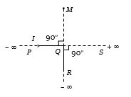
- 10An infinitely long conductor $PQR$ is bent to form a right angle as shown. A current $I$ flows through $PQR$ The magnetic field due to this current at the point $M $ is $H_1$. Now another infinitely long straight conductor $QS$ is connected at $Q$ so that the current is $I/2$ in $QR$ as well as in $QS$, The current in $PQ$ remaining unchanged. The magnetic field at $M$ is now ${H_{2.}}$The ratio ${H_1}/{H_2}$ is given byView Solution