Questions

Answer the following in Detail

Take a timed test

11 questions · self-marked practice — reveal the answer and mark yourself.

Question 14 Marks
Explain the phenomenon of self induction and mutual induction. Define coefficient of self induction and mutual induction. Write the SI unit and dimensions of coefficient of self induction
Answer
phenomenon of self induction:
a. The phenomenon of production of an induced e.m.f in a coil due to change in current in the same coil is called self induction. It is also called as back-e.m.f.
b.
Image
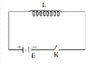
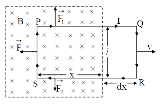
Consider a coil connected with battery E, plug key K and inductor L carrying current of magnitude I as shown in figure.
c. Since magnetic flux linked with the coil is directly proportional to the current,
$\therefore φ ∝ I$
$\therefore φ = LI .…(i)$
where, L = constant called coefficient of self induction or self inductance of the coil, which depends upon the number of turns, shape, area of the coil and material of the core.
d. Induced e.m.f in the coil is given by,
\(e=-\frac{d \phi}{d t}\)
\(e=-L \frac{d I}{d t}\)….(ii)
−ve sign in equation (ii) shows that self induced e.m.f opposes the rate of change of current.
\(\therefore|e|=\left|-L \frac{d I}{d t}\right|\)
\(\therefore|e|=L \frac{d I}{d t}\)
∴ Magnitude of self induced e.m.f is given by, \(e=L \frac{d I}{d t}\)
This is required induced e.m.f.
phenomenon of mutual induction:
a. The phenomenon of production of induced e.m.f in one coil due to change of current in the neighbouring coil is called mutual induction. The e.m.f so induced is called mutually induced e.m.f.
b.
Image
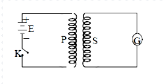
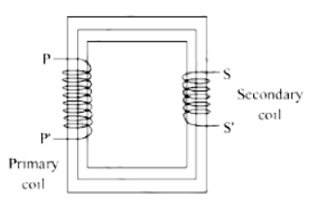
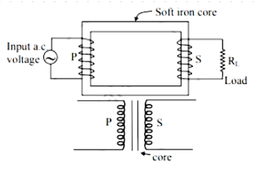
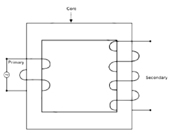
Consider primary coil P and secondary coil S fitted with galvanometer G and placed very close to each other as shown in figure. The coil P is connected in series with the source of e.m.f (battery) and key K.
c. When tap key K is pressed, current IP passes through the coil P. Magnetic flux φS linked with secondary coil S at any instant is directly proportional to current IP through primary coil P at that instant.
$\therefore φS ∝ IP$
$\therefore φS = M I_P ….(i)$
where M is constant called coefficient of mutual induction or mutual inductance of the coil.
d. e.m.f induced in S at any instant is given by,
\(e_S=-\frac{d \phi_s}{d t}\)
\(e_S=-\frac{d}{d t}\left(M I_P\right)\) [From equation (i)]
\(\therefore e_S=-M \frac{d I_P}{d t}\)
∴ Magnitude of induced e.m.f is given by,
\(\left|e_S\right|=\left|-\frac{M d I_P}{d t}\right|\)
\(e_s=\frac{M d I_P}{d t}\)
\(M=\frac{e_S}{\frac{d I_P}{d t}}\)
coefficient of self-induction:
The definition of self-inductance is the induction of a voltage in a wire that carries current when the current in the wire is changing.
coefficient of mutual induction:
Coefficient of mutual induction is defined as the e.m.f induced in the secondary coil per unit rate of change of current in the primary coil (neighbouring coil).
SI unit and dimention of of co-efficient of self induction:
SI Unit of co-efficient of self induction is henry (H) in SI system or volt $A−1$ s.
Dim ensions of self induction are$ [L^2M^1T^{−2}A^{−2}]$
View full question & answer
Question 24 Marks
Obtain an expression for the induced e.m.f. in a coil rotating with uniform angular velocity in uniform magnetic field. Plot a graph of variation of induceed e.m.f. against phase (0= wt) over one cycle.
Answer
a) Consider a rectangular loop of conducting wire ‘PQRS’ partly placed in uniform
magnetic field of induction ‘B’ as shown in figure.
Image
b) Let ‘l’ be the length of the side PS and ‘x’ be the length of the loop within the field.
∴ A = lx = area of the loop, which lies inside the field.
c) The magnetic flux (φ) through the area A at certain time ‘t’ is Φ = BA = Blx
d) The loop is pulled out of the magnetic field of induction ‘B’ to the right with a uniform
velocity ‘v’.
e) The rate of change of magnetic flux is given by, \(\frac{d \phi}{d t}=\frac{d}{d t}(B l x)\)
\(\therefore \quad \frac{ d \phi}{ dt }= B l\left(\frac{ dx }{ dt }\right)\)
But, \(\left(\frac{d x}{d t}\right)=v\)
\(\therefore \quad \frac{ d \phi}{ dt }= B / v\)...(i)
f) Due to change in magnetic flux, induced current is set up in the coil. The direction of
this current is clockwise according to Lenz’s law. Due to this, the sides of the coil
experience the forces, F1, F2 and F as shown in figure. The directions of these forces is
given by Fleming’s left hand rule.
g) The magnitude of force ‘F’ acting on the side PS is given by, F = BIl.
h) The force \(\vec{F}_1\)  and \(\vec{F}_2\) are equal in magnitude and opposite in direction, therefore they cancel out. The only unbalanced force which opposes the motion of the coil is \(\vec{F}\) Hence, work must be done against this force in order to pull the coil.
i) The work done in time ‘dt’ during the small displacement ‘dx’ is given by, dW = −Fdx
− ve sign shows that F and ‘dx’ are opposite to each other.
∴ dW = − (BIl) dx ….(ii)
j) Mechanical power is given by,
\(P =\frac{ dW }{ dt }= BI l\left(\frac{ dx }{ dt }\right)\)
\(\therefore \quad P = BI / v \quad\left[\because \frac{ dx }{ dt }= v \right]\)
k) This external work provides the energy needed to maintain the induced current I
through the loop (coil).
l. If ‘e’ is the e.m.f induced then,
electric power \(=\frac{d W}{d t}=e I\)
∴ dW = eIdt .…(iii)
m) From equations (ii) and (iii), we have, eIdt = − BIl dx
\(\therefore e=-B l \frac{d x}{d t}\)
\(\therefore e =- B / v \ldots\) (iv)
n. From equation (i) and (iv), we have,
\(e=-\frac{d \phi}{d t}\)
o) Graph of variation of induced e.m.f. against phase (θ = ωt) over one cycle
Image
View full question & answer
Question 34 Marks
Prove theoretically, the relation between e.m.f. induced and rate of change of magnetic flux in the electric circuit in electromagnetic induction.
Answer
Image
Magnetic flux Φ = NABcos ωt
N → No.s of turns
A → Area of a coil
B → Magnetic field {external}
ω → Angular speed of the coil
\(\therefore \max \phi_0=N A B, \omega t \rightarrow 0\)
\(\therefore \phi=\phi_0 \cos \omega t\)
induce \(\operatorname{EMF}( e )\)
\(e =-\frac{d \phi}{d t}=+\omega N A B \sin \omega t\)
\(e_0=\omega N A B, \omega t \rightarrow 90\)
\(\therefore e=e_0 \sin \omega t\)
So there is phase difference of \(\frac{\pi}{2}\) with \(\phi\) and e
 
View full question & answer
Question 44 Marks
What is transformer? With the help of suitable diagram describe working of transformer.
Answer
A transformer is a device used for changing the voltage of alternating current from low value to high value or vice versa.
It works on the principle of mutual induction. Here, a changing alternating current in primary coil produces a changing magnetic field, which, in turn, induces a changing alternating current in the secondary coil.
Image
View full question & answer
Question 54 Marks
What is series LCR circuit? Obtain the expression for impedance. Hence state the conditions for series resonance and derive the expression for resonant frequency.
Answer
An LCR circuit is a circuit that contains inductance (L), capacitance (C), and resistance (R) components connected in series. It's a fundamental circuit used in electronics and electrical engineering for various applications like filtering, oscillators, and signal processing.
Impedance in an LCR Circuit
The total impedance (Z) in a series LCR circuit is the total opposition to the flow of alternating current. It's a complex quantity and is calculated as the vector sum of the individual impedances of the inductor \(\left(Z_L\right)\),capacitor \(\left(Z_C\right)\),and resistor \(\left(Z_R\right)\).
The impedance expressions for each component in a series LCR circuit are:
Inductive impedance: \(Z_L=j \omega L\)
Capacitive impedance:\(Z_C=1 /(j \omega C)\)
Resistive impedance: \(Z_R=R\)
The total impedance in a series LCR circuit is given by the formula:\(Z=\sqrt{\left(Z_L=Z_C+Z+R\right)^2}\)
Conditions for Series Resonance
Series resonance in an LCR circuit occurs when the inductive reactance \(\left(X_L\right)\) equals the capacitive reactance \(\left(X_C\right)\) and the circuit's impedance reaches its minimum value. This happens when \(X_L=X_C\).
Conditions are:
\(X_L=X_C\)
At resonance, net reactance \(\left(X_L-X_C\right)=0\).
The total impedance of the circuit is equal to the resistance \((Z=R)\).
Derivation of Resonant Frequency
At resonance, \(X_L=X_C\)
\(X_L=\omega L\)
\(X_C=1 /(\omega C)\)
∴ After substitution,
\(\omega L=1 /(\omega C)\)
\(\omega=1 /(\sqrt{L C})\)
Hence, the expression for the resonant frequency in a series LCR circuit is
\(\omega_0=1 /(\sqrt{L C})\)
View full question & answer
Question 64 Marks
State the principle of working of transformer. Explain the construction and working of a transfer. Derive an expression for e.m.f. and current in terms of turns ratio.
Answer
The working principle of the transformer is the mutual induction. The magnetic flux linked with the primary winding of the transformer must change, to produce an induced emf in the secondary coil.
Principle:
It is based on the principle of mutual induction i.e., whenever the magnetic flux linked with a coil changes, an e.m.f is induced in the neighbouring coil.
  1. Construction:
    a. A transformer consists of two sets of coils primary P and secondary S insulated from each other. Coil P is called the input coil and coil S is called the output coil.
    b. The two coils are wound separately on a laminated soft iron core.
Image
2. Working:
a. When an alternating voltage is applied to the primary coil the current through the coil goes on changing. Hence, the magnetic flux through the core also changes.
b. As this changing magnetic flux is linked with both the coils, an e.m.f is induced in each coil.
c. The amount of the magnetic flux linked with the coil depends upon the number of turns of the coil.
d. Let, $‘Φ’$ be the magnetic flux linked per turn with both the coils at a certain instant $‘t’.$
e. Let $‘N_P'$ and $‘N_S’$ be the number of turns of the primary and secondary coil,
$N_PΦ$ = magnetic flux linked with the primary coil at a certain instant $‘t’$
$N_SΦ$ = magnetic flux linked with the secondary coil at a certain instant $‘t’$
f. Induced e.m.f produced in the primary and secondary coil is given by,
\(e_p=-\frac{d \phi_p}{d t}=-N_p \frac{d \phi}{d t} \ldots .(1)\)
\(e_s=-\frac{d \phi_{ s }}{d t}=-N_s \frac{d \phi}{d t} \ldots . .(2)\)
g. Dividing equation (2) by (1),
\(\therefore \frac{ e _{ s }}{ e _{ p }}=\frac{ N _{ s }}{ N _{ p }} \ldots .(3)\)
Equation (3) represents equation of transformer.
The ratio \(\frac{N_s}{N_p}\) is called turns ratio (transformer ratio) of the transformer.
h. For an ideal transformer,
Input power = Output power
$\therefore e_PI_P = e_SI_S$
\(\therefore \frac{ e _{ s }}{ e _{ p }}=\frac{ I _{ p }}{ I _{ s }} \ldots\)(4)
i. From equation (3) and (4),
\(\frac{e_s}{e_p}=\frac{N_s}{N_p}=\frac{I_p}{I_s}\)
Expression for e.m.f and current :
1. Let, \(\phi\) be the magnetic flux linked per turn with both the coils at certain instant ' \(t\) '
2. Let ‘NP and ‘NS’ be the number of turns of primary and secondary coil,
\(N_P \phi=\) magnetic flux linked with the primary coil at certain instant ' \(t\) '
\(N _{S \phi}=\) magnetic flux linked with the secondary coil at certain instant ' \(t\) '
3. Induced e.m.f produced in the primary and secondary coil is given by,
\(e_p=-\frac{d \phi_p}{d t}=-N_p \frac{d \phi}{d t} \ldots\)(1)
\(e_s=-\frac{d \phi_s}{d t}=-N_s \frac{d \phi}{d t} \ldots \ldots\) (2)
4. Dividing equation (2) by (1),
\(\frac{e_s}{e_p}=\frac{N_s}{N_p} \ldots\) (3)
Equation (3) represents equation of transformer.
The ratio \(\frac{N_s}{N_p}\) is called turns ratio (transformer ratio) of the transformer
5. For an ideal transformer,
Input power = Output power
6. \(e_p I_p=e_s I_s\)
\(\frac{e_s}{e_p}=\frac{I_p}{I_s}\)......(4)
7. From equation (3) and (4),
\(\frac{e_s}{p_p}=\frac{N_s}{N_p}=\frac{I_p}{I_s}\)
View full question & answer
Question 74 Marks
What is electromagnetic induction? Prove theoretically \(e=-\frac{ d \phi}{ d t}\).
Answer
The phenomenon of producing an induced e.m.f in a conductor or conducting coil due to changing magnetic flux is called electromagnetic induction.
1) Consider a rectangular loop of conducting wire ‘PQRS’ partly placed in uniform magnetic field of induction ‘B’ as shown in figure.
Image
2) Let 'l' be the length of the side PS and 'x' be the length of the loop within the field.
∴ A = lx = area of the loop, which lies inside the field.
3) The magnetic flux (Φ) through the area A at certain time ‘t’ is Φ = BA = Blx
4) The loop is pulled out of the magnetic field of induction ‘B’ to the right with a uniform
velocity ‘v’.
5) The rate of change of magnetic flux is given by, \(\frac{d \phi}{d t}=\frac{d}{d t}\left(\frac{B}{x}\right)\)
\(\therefore \frac{d \phi}{d t}=B l\left(\frac{d x}{d t}\right)\)
But, \(\left(\frac{d x}{d t}\right)=v\)
\(\therefore \frac{d \phi}{d t}= Blv\) ....(1)
6) Due to change in magnetic flux, induced current is set up in the coil. The direction of this current is clockwise according to Lenz’s law. Due to this, the sides of the coil experiences the forces, $F_1, F_2$ and $F$ as shown in figure. The directions of these forces is given by Flemings left hand rule.
7) The magnitude of force $‘F’$ acting on the side PS is given by, $F = BIl.$
8)The force \(\vec{F}_1\) and \(\vec{F}_2\) are equal in magnitude and opposite in direction, therefore they cancel out. The only unbalanced force which opposes the motion of the coil is \(\vec{F}\) Hence, work must be done against this force in order to pull the coil.
9) The work done in time ‘dt’ during the small displacement $‘dx’$ is given by, $dW = - Fdx - ve$ sign shows that $F$ and $‘dx’$ are opposite to each other.
$\therefore dW = - (BIl) dx ….(2)$
10) This external work provides the energy needed to maintain the induced current I
through the loop (coil).
11) If ‘e’ is the e.m.f induced then, electric power = \(\frac{d W}{d t}=e I\)
$\therefore dW = eIdt ....3$
12) From equations (2) and (3),
eIdt = - BIl dx
\(\therefore e=-B l\left(\frac{d x}{d t}\right)\)
\(\therefore e =- Blv . . . .(4)\)
13) From equation (1) and (4), \(e=-\frac{d \phi}{d t}\)
View full question & answer
Question 84 Marks
State the principle on which transformer works. Explain its working with construction. Derive an expression for ratio of e.m.f.s and currents in terms of number of turns in primary and secondary coil.
Answer
A transformer is a device with the help of which, a given alternating voltage can be increased or decreased to any desired value. The first type of transformer which delivers an output voltage smaller than the input voltage
is called a step down transformer. The second type of transformer which delivers an output voltage larger than the input voltage is called a step up transformer.
Principle of working of a transformer:
A transformer works on the principle that whenever the magnetic flux linked with a coil changes, an emf is induced in the neighbouring coil.Construction:
It consists of two coils, primary (P) and secondary (S), insulated from each other and wound on a soft iron core as shown in the figure below.
Image
The primary coil is called the input coil and the secondary coil is called the output coil.
Working:
When an alternating voltage is applied to the primary coil, the current through the coil goes on changing. Hence, the magnetic flux through the core also changes. As this changing magnetic flux is linked with both coils, an emf is induced in each of them. The amount of magnetic flux linked with the coil depends on the number of turns of the coil.Derivation:
Let ‘$Φ$’ be the magnetic flux linked per turn with both coils at a certain instant of time $‘t’.$
Let the number of turns of the primary and secondary coils be $‘N_p’$ and $‘N_s’$, respectively.
Therefore, the total magnetic flux linked with the primary coil at certain instant of time $‘t’$ is $N_pΦ$. Similarly, the total magnetic flux linked with the secondary coil at certain instant of time $‘t’$ is $N_sΦ$.
Now, the induced emf in a coil is
\(e=\frac{d \phi}{d t}\)
Therefore, the induced emf in the primary coil is
\(e_p=\frac{d \phi_p}{d t}=\frac{d N_p \phi}{d t}=-N_p \frac{d \phi}{d t}\).......(1)
Similarly, the induced emf in the secondary coil is
\(e_s=\frac{d \phi_s}{d t}=\frac{d N_s \phi}{d t}=-N \frac{d \phi}{d t}\).......(2)
Dividing equations (1) and (2), we get
\(\frac{e_s}{e_p}=\frac{-N_s \frac{d \phi}{d t}}{-N_p \frac{d \phi}{d t}}=\frac{N_s}{N_p}\)........(3)
The above equation is called the equation of the transformer and the ratio \(\frac{N_s}{N_p}\) is known as the turns ratio of the transformer.
Now, for an ideal transformer, we know that the input power is equal to the output power.
\(\therefore P_p=P_s\)
\(\therefore e_p i_p=e_s i_s\)
\(\therefore \frac{e_s}{e_p}=\frac{i_p}{i_s}\)
From equation (3), we have
\(\frac{e_s}{e_p}=\frac{N_s}{N_P}\)
\(\therefore \frac{e_s}{e_p}=\frac{N_s}{N_p}=\frac{i_p}{i_s}\)
View full question & answer
Question 94 Marks
Obtain an expression for e.m.f. induced in a coil rotating with uniform angular velocity in a uniform magnetic field. Show graphically the variation of e.m.f. with time (t).
Answer
Coil rotating in uniform magnetic field:
Consider a coil of ‘N’ turns with effective area NA placed in uniform magnetic induction B as shown in the figure below.
Image
The coil is rotated continuously with constant angular velocity ω. The axis of rotation is in the plane of the coil and normal to the magnetic induction B.
At t = 0, the plane of the coil is perpendicular to the magnetic induction B.
The magnetic flux passing through the coil is NAB.
After t seconds, the plane of the coil is at an angle θ.
Thus, the magnetic flux Φ through the coil at time t is given by
Φ = NABcosθ = NABcosωt
As time changes, the magnetic flux goes on changing. Hence, the e.m.f. generated in the coil is given by
\(e=-\frac{d \phi}{d t}=-\frac{d}{d t}(N A B \cos \omega t)\)
e = NABωsinωt
e = 2πfNABsinωt
This is the expression for induced e.m.f. generated in the coil at any instant t. It is known as instantaneous e.m.f.
Image
Given that
$R/L = \sigma = 0.1Ω/cm = 0.1 x 100 = 10Ω/m$
$l_1 = 300 cm = 3 m, E_1 = 1.5 V, E_2= 1.4 V$
We know that
$E_1 = iR_1 =i\sigma l_1$
\(\therefore i=\frac{E_1}{\sigma l_1}=\frac{1.5}{10 \times 3}=0.05 A\)
Hence, the current for the other cell is 0.05 A.
For potentiometer, the balancing condition is
\(\frac{E_1}{E_2}=\frac{l_1}{l_2}\)
\(\therefore l_2=l_1 \frac{E_2}{E_1}=3 \times \frac{1.4}{1.5}=2.8 m\)
So, the balancing length for the other cell is 2.8 m.
View full question & answer
Question 104 Marks
State the principle of a transformer. Explain its construction and working. Derive an expression for the ratio of e.m.f.s in terms of number of turns in primary and secondary coil.
Answer
A transformer is a device with the help of which, a given alternating voltage can be increased or decreased to any desired value. The first type of transformer which delivers an output voltage smaller than the input voltage
is called a step down transformer. The second type of transformer which delivers an output voltage larger than the input voltage is called a step up transformer.
Principle of working of a transformer:
A transformer works on the principle that whenever the magnetic flux linked with a coil changes, an emf is induced in the neighbouring coil.Construction:
It consists of two coils, primary (P) and secondary (S), insulated from each other and wound on a soft iron core as shown in the figure below.
Image
The primary coil is called the input coil and the secondary coil is called the output coil.
Working:
When an alternating voltage is applied to the primary coil, the current through the coil goes on changing. Hence, the magnetic flux through the core also changes. As this changing magnetic flux is linked with both coils, an emf is induced in each of them. The amount of magnetic flux linked with the coil depends on the number of turns of the coil.Derivation:
Let $‘Φ’$ be the magnetic flux linked per turn with both coils at a certain instant of time $‘t’.$
Let the number of turns of the primary and secondary coils be $‘N_p’$ and $‘N_s’$, respectively.
Therefore, the total magnetic flux linked with the primary coil at certain instant of time $‘t’$ is $N_pΦ$. Similarly, the total magnetic flux linked with the secondary coil at certain instant of time $‘t’$ is $N_sΦ.$
Now, the induced emf in a coil is
\(e=\frac{d \phi}{d t}\)
Therefore, the induced emf in the primary coil is
\(e_p=\frac{d \phi_p}{d t}=\frac{d N_p \phi}{d t}=-N_p \frac{d \phi}{d t}\).......(1)
Similarly, the induced emf in the secondary coil is
\(e_s=\frac{d \phi_s}{d t}=\frac{d N_s \phi}{d t}=-N \frac{d \phi}{d t}\).......(2)
Dividing equations (1) and (2), we get
\(\frac{e_s}{e_p}=\frac{-N_s \frac{d \phi}{d t}}{-N_p \frac{d \phi}{d t}}=\frac{N_s}{N_p}\)........(3)
The above equation is called the equation of the transformer and the ratio \(\frac{N_s}{N_p}\) is known as the turns ratio of the transformer.
Now, for an ideal transformer, we know that the input power is equal to the output power.
\(\therefore P_p=P_s\)
\(\therefore e_p i_p=e_s i_s\)
\(\therefore \frac{e_s}{e_p}=\frac{i_p}{i_s}\)
From equation (3), we have
\(\frac{e_s}{e_p}=\frac{N_s}{N_P}\)
\(\therefore \frac{e_s}{e_p}=\frac{N_s}{N_p}=\frac{i_p}{i_s}\)
View full question & answer
Question 114 Marks
Derive an expression for energy stored in the magnetic field in terms of induced current.
A wire $5 m$ long is supported horizontally at a height of $15 m$ along east$-$west direction. When it is about to hit the ground, calculate the average e.m.f. induced in it. $\left( g =10 \ m / s ^2\right)$
Answer
$1.$ An induced emf is produced when the magnetic flux in a coil changes.
$2.$ The induced emf produced opposes the change and thus the energy expended to resist it in order to build up the magnetic field.
$3.$ This energy can be recovered as heat in the circuit's resistance.
$4.$ We know that, $e=-L \frac{d I}{d t}$
$5.$ The work done in moving a charge dq against this emf is
$\therefore dw =- e.dq = L \frac{d I}{d t} \cdot d q=L \cdot \frac{d I d q}{d t}$
$\therefore dw = L.I.dl ...........\left(\therefore \frac{d q}{d t}=I\right)$
Therefore, the total work is given by,
$W =\int d w=\int_0^1 L \cdot I \cdot d I$
$\therefore W =\frac{1}{2} L I^2=U_B$
$6$. This is the energy stored $(U_B)$ in the magnetic field.
Given:
$h = 15 m, l = 5 m, g = 10 \ m/s^2, e =$ ?
Formula:
$e = Blv$
The magnetic flux density $(B)$ due to the earth's magnetic field is about $3.6 \times 10^{-5} T.$
Assuming that the wire is falling vertically under the influence of gravity, we can use the free fall equation to find the velocity $(v).$
$\therefore v =\sqrt{2 g h}=\sqrt{2 \times 10 \times 15}=17.32 \ m / s$
Now, $e = Blv = 3.6 \times 10^{-5} \times 5 \times 17.32$
$\therefore e = 3.1176 \times 10^{-3}$ volts
View full question & answer