- Draw a schematic diagram of a reflecting telescope.
- State the advantages of reflecting telescope over refracting telescope.
CBSE OUTSIDE DELHI - SET 1 EAST 2016
Download our app for free and get started
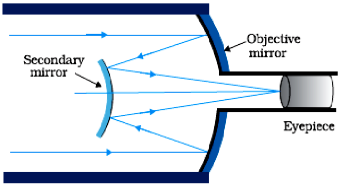
- Advantages:
- There is no chromatic aberration in a mirror.
- Brighter image.
- High resolving Power.
- Large light gathering power.
- Large magnifying power.

Download our appand get started for free
Experience the future of education. Simply download our apps or reach out to us for more information. Let's shape the future of learning together!No signup needed.*
Similar Questions
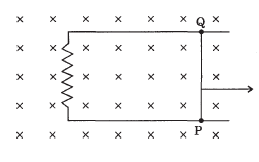
- 1View SolutionA 0’5 m long metal rod PQ completes the circuit as shown in the figure. The area of the circuit is perpendicular to the magnetic field of flux density 0-15 T. If the resistance of the total circuit is 3Ω, calcularod in the direction as indicated with a constant speed ofte the force needed to move the rod in the direction as indicated with a constant speed of 2ms−1.
- 2View SolutionObtain the resonant frequency and Q-factor of a series LCR circuit with L = 3.0H, C = 27μF, and R = 7.4Ω. It is desired to improve the sharpness of the resonance of the circuit by reducing its ‘full width at half maximum’ by a factor of 2. Suggest a suitable way.
- 3View SolutionBoth alternating current and direct current are measured in amperes. But how is the ampere defined for an alternating current?
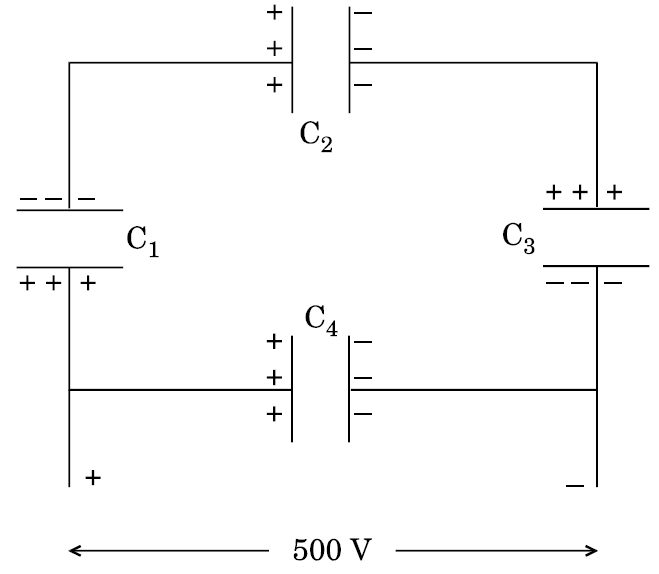
- 4A network of four 10 $\mu$F capacitors is connected to a 500 V supply as shown in the figure. Determine theView Solution
- equivalent capacitance of the network and.
- charge on each capacitor.
- 5View SolutionAn electric bulb is designed to operate at 12 volts DC. If this bulb is connected to an AC source and gives normal brightness, what would be the peak voltage of the source?
- 6An AC voltage $V = V_m$ is applied across a:View Solution
- Series RC circuit in which capacitive reactance is ‘a’ times the resistance in the circuit.
- Series RL circuit in which inductive reactance is ‘b’ times the resistance in the circuit.
- 7View SolutionCompare and explain three distinguishing features observed in Young’s double slit interference pattern with those seen for a coherently illuminated single slit producing diffraction pattern.
- 8An inductor 200mH, a capacitor $100\mu\text{F}$ and a resistor $10\Omega$ are connected in series to an a.c. source of 100V, having variable frequency.View Solution
- At what frequency of the applied voltage will the power factor of the circuit be 1?
- What will be the current amplitude at this frequency?
- Calculate the Q-factor of the circuit.
- 9An AC source of voltage $\text{V = Vm}\sin\omega\text{t}$ is applied across a series LCR circuit. Draw the phasor diagrams for this circuit, when,View Solution
- Capacitive impedance exceeds the inductive impedance.
- Inductive impedance exceeds capacitive impedance.
- 10View SolutionHow is a galvanometer converted into a voltmeter and an ammeter? Draw the relevant diagrams and find the resistance of the arrangement in each case. Take resistance of galvanometer as G.