A metallic rod of length ‘l’ is rotated with a frequency ‘v’, with one end hinged at the centre and the other end at the circumference of a circular metallic ring, about an axis passing through the centre and perpendicular to the plane of the ring. A constant and uniform magnetic field B parallel to the axis is present everywhere.
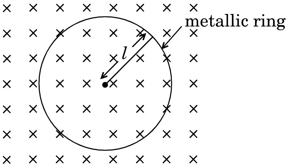
- Obtain the expression for the emf induced between the centre and the ring.
- Given that the rod has resistance ‘R’, then how much power will be generated?
CBSE OUTSIDE DELHI - SET 3 GUHAWATI 2015
Download our app for free and get started
- Emf induced $\int^{1}_{0}\text{Bwrdr}$
$\because \omega = 2\pi\text{v}$
$\therefore\varepsilon = \pi\text{Bvl}^{2}$
- $\text{P} = \frac{\varepsilon^2}{\text{R}} = \frac{(\pi\text{Bvl}^{2})^{2}}{\text{R}}$

Download our appand get started for free
Experience the future of education. Simply download our apps or reach out to us for more information. Let's shape the future of learning together!No signup needed.*
Similar Questions
- 1View SolutionFigure shows a light bulb (B) and iron cored inductor connected to a dc battery through a switch (S).
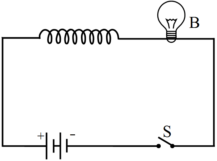
- What will one observe when switch (S) is closed?
- How will the glow of the bulb change when the battery is replaced by an ac source of rms voltage equal to the voltage of dc battery? Justify your answer in each case.
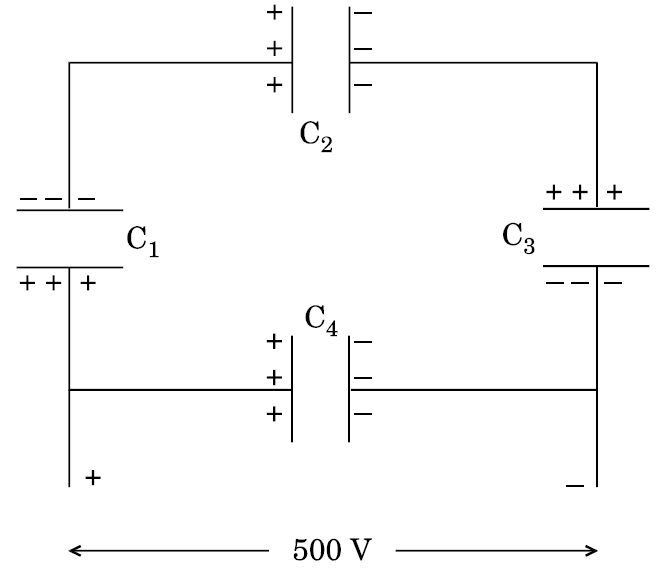
- 2A network of four 10 $\mu$F capacitors is connected to a 500 V supply as shown in the figure. Determine theView Solution
- equivalent capacitance of the network and
- charge on each capacitor
- 3View Solution
- A screen is placed at a distance of 100 cm from an object. The image of the object is formed on the screen by a convex lens for two different locations of the lens separated by 20 cm. Calculate the focal length of the lens used.
- A converging lens is kept coaxially in contact with a diverging lens - both the lenses being of equal focal length. What is the focal length of the combination?
- 4View SolutionExplain with the help of a labelled diagram the underlying principle and working of a step-up transformer. Why cannot such a device be used to step-up d.c. voltage?
- 5View Solution
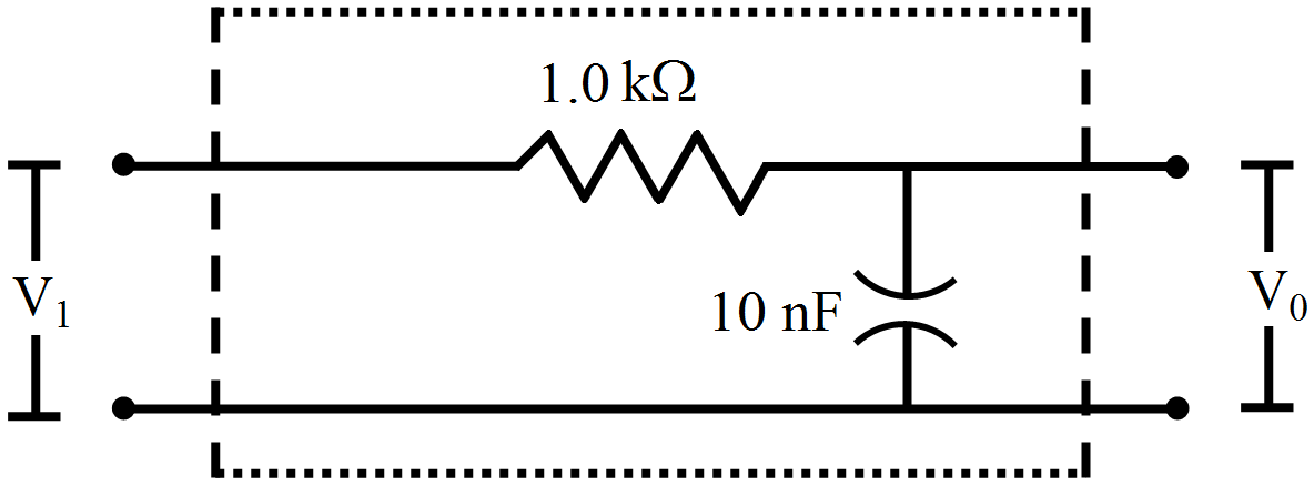
Figure shows a typical circuit for a low-pass filter. An AC input $V_{i }= 10mV$ is applied at the left end and the output $V_0$ is received at the right end. Find the output voltage for ν = 10kHz, 1.0MHz and 10.0MHz. Note that as the frequency is increased the output decreases and, hence, the name low-pass filter.
- 6View SolutionObtain the resonant frequency and Q-factor of a series LCR circuit with L = 3.0H, C = 27μF, and R = 7.4Ω. It is desired to improve the sharpness of the resonance of the circuit by reducing its ‘full width at half maximum’ by a factor of 2. Suggest a suitable way.
- 7View SolutionIn the given circuit, the potential difference across the inductor L and resistor R are 200V and 150V respectively and the rms. value of current is 5A. Calculate (i) the impedance of the circuit and (ii) the phase angle between the voltage and the current.
- 8A series LCR circuit is connected across an a.c. source of variable angular frequency $' \omega'$. Plot a graph showing variation of current ‘i’ as a function of $' \omega'$ for two resistances $R_1$ and $R2 (R_1 > R_2).$View Solution
Answer the following questions using this graph:- In which case is the resonance sharper and why?
- In which case is the power dissipation more and why?
- 9View SolutionHow are electromagnetic waves produced? What is the source of energy of these waves? Draw a schematic sketch of the electromagnetic waves propagating along the + x-axis. Indicate the directions of the electric and magnetic fields. Write the relation between the velocity of propagation and the magnitudes of electric and magnetic fields.
- 10View SolutionUsing truth tables of AND gate and NOT gate show that NAND gate is an AND gate followed by a NOT gate. Hence write the truth table of NAND gate.
Why are NAND gates called ‘Universal Gates’?