Question 11 Mark
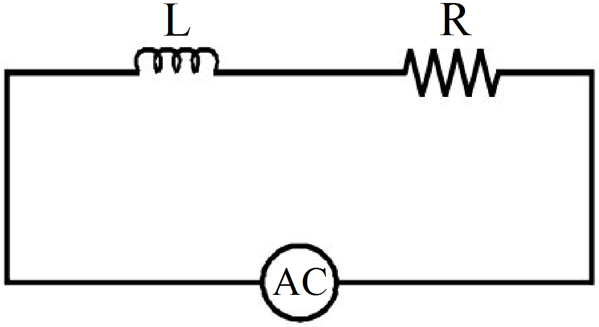
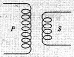
Symbol of Inductance in electric circuit is-
Answer

Explanation:
A is for resitance, B is for inductance, C is for a switch and D is for Galvanometer.
View full question & answer→Question 21 Mark
Which one of the following graphs in following figure represents variation of reactance $′X_c\ ′$ of a capacitor with frequency $'f\ '$ of an ac supply?
Answer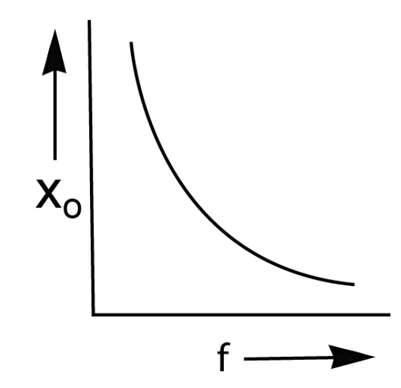
Capacitor reactance is given by: $\text{X}_\text{c}=\frac{1}{2\pi\text{fC}}$
$C$ is the capacitance.
$X_{c } f$ are inversely proportional. View full question & answer→Question 31 Mark
With increase in frequency of an A.C. supply, the inductive reactance.
Answer
- increases directly with frequency
Explanation:
The inductive reactance $\text{Xl}=\omega\text{L}$
Hence, $\text{X}_1\propto\omega$
As frequency increases $\rightarrow\omega$
Therefore, inductive reactance increases with frequency. View full question & answer→Question 41 Mark
The line that draws power supply to your house from street has:
Answer
- Zero average current.
- Voltage and current possibly differing in phase $\phi$ such that $\Big|\phi\Big|<\frac{\pi}{2}$.
Solution:
Alternation currents are used for household supplies, which are having zero average value over a cycle.
The line is having some resistance, so power factor $\cos\phi=\frac{\text{R}}{\text{Z}}\neq0$
So, $\phi\neq\frac{\pi}{2}\Rightarrow\ \phi<\frac{2}{\pi}$
i.e., phase lies between 0 and $\frac{\pi}{2}$.
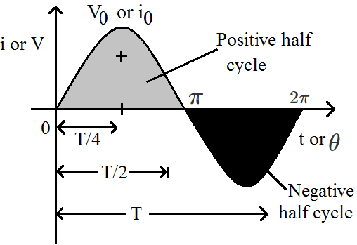
Important point: The average value of alternating quantity for one complete cycle is zero.
The average value of ac over half cycle $\Big(\text{t}=0\text{ to }\frac{\text{T}}{2}\Big)$
$\text{i}_\text{av}=\frac{\int_0^{\frac{\text{T}}{2}}\text{idt}}{\int_0^{\frac{\text{T}}{2}}\text{dt}}=0.637\text{i}_0=63.7\% \ \text{of i}_0$
Similarly $\text{V}_\text{av}=\frac{2\text{V}_0}{\pi}=0.637\text{V}_0=63.7\%\ \text{of V}_0.$ View full question & answer→Question 51 Mark
When a voltage measuring device is connected to $AC$ mains, the meter shows the steady input voltage of $220V.$ This means,
AnswerThe meter reads not $v$ but $< v^2 >$ and is calibrated to read $\sqrt{<\text{v}^2>}$.
View full question & answer→Question 61 Mark
The AC produced in India changes its direction in every:
Answer
- $\frac{1}{100}\text{second}$
Explanation:
In India, the frequency of AC voltage is 50 Hz.
It means 50 waves will be produced in 1 s.
In one wave, the direction is changed 2 times.
Thus, in 50 waves, the direction will be altered 50 × 2 = 100 times.
i.e. the direction is changed 100 times in 1 s.
Thus the direction is changed in every $\frac{1}{100}\text{second}$ View full question & answer→Question 71 Mark
To reduce the reasonant frequency in an LCR series circuit with a generator:
Answer
- Another capacitor should be added in parallel to the first.
Solution:
Key Concept: Resonant frequency (Natural frequency)
At resonance $\text{X}_\text{L}=\text{X}_\text{C}\Rightarrow\ \omega_0\text{L}=\frac{1}{\omega_0\text{C}}$
$\Rightarrow\ \omega_0=\frac{1}{\sqrt{\text{LC}}}\frac{\text{red}}{\sec}$
$\Rightarrow\ \text{v}_0=\frac{1}{2\pi\sqrt{\text{LC}}}\text{Hz}$
Resonant frequency in an L-C-R circuit is given by
$\text{v}_0=\frac{1}{2\pi\sqrt{\text{LC}}}$
If L or C increases, the resonant frequency will reduce.
To increase capacitance, we must connect another capacitor parallel to the first. View full question & answer→Question 81 Mark
An AC voltmeter in an L - C - R circuit reads 30volt across resistance, 80 volt across inductance and 40 volt across capacitance. The value of applied voltage will be.
Answer
- 50 Volt
Explanation:
$\text{V}=\sqrt{\text{V}^2_\text{R}+(\text{V}_\text{L}-\text{V}_\text{C})^2}$
$\text{V}=\sqrt{30^2+(80-40)^2}$
$\text{V}=50\text{ Volt}$ View full question & answer→Question 91 Mark
In series combination of R, L, C with an A.C source at resonanace, if R = 20 ohm, then impedence Z of the combination is.
Answer
- 20 ohm
Explanation:
We know at resonance, reactance (resistance due to inductor and capacitor) be zero (0).
At resonance, Impedance (Z) = Resistance (R)
Therefore, Z = 20 ohm
View full question & answer→Question 101 Mark
In an LCR circuit the capacitance is made $\frac{1^\text{th}}{4}$ then what should be the change in inductance that the circuit remains in resonance again?
Answer
- 4 times
Explanation:
$\text{f}_0=\frac{1}{2\pi\sqrt{\text{LC}}}.$ View full question & answer→Question 111 Mark
In an LCR circuit the potential difference between the terminal of the inductance is 60V, between the terminals of the capacitor is 30V and that between the terminals of the resistance is 40V. The supply voltage will be equal to:
Answer
- 50V
Explanation:
Supply voltage of an LCR circuit
$\text{V}=\sqrt{\text{V}^2_\text{R}+(\text{V}_\text{L}-\text{V}_\text{C})^2}$
since inductor and capacitor potentials are out of phase with each other
$=\sqrt{40^2+(60-30)^2\text{V}}$
$=50\text{V}$ View full question & answer→Question 121 Mark
The values of $X_L, X_{C }$ and $R$ in series with an $A.C.$ circuit are $8\Omega,6\Omega$ and $10\Omega$ respectively. The
total impedance of the circuit will be $..........\Omega$
Answer$\text{Z}=\sqrt{\text{R}^2+(\text{X}_\text{L}-\text{X}_\text{C})^2}$
$=\sqrt{(10)^2+(8-6)^2}$
$=\sqrt{10^2+2^2}$
$=\sqrt{100+4}$
$=10.2\Omega$
View full question & answer→Question 131 Mark
Of the following about capacitive reactance which is correct?
Answer
- Capacitive reactance is inversely proportional to the frequency of the current
Explanation:
Capacitative reactance is an opposition to the change of voltage across an element.
It is denoted by XC and is inversely proportional to the signal frequency (f) and the capacitance C
$\text{X}_\text{c}=\frac{1}{2\pi\text{fc}}$ View full question & answer→Question 141 Mark
A current source sends a current $\text{I}-\text{i}_0\cos(\omega\text{t}).$ when connected across an unknown load, it gives a voltage output of $\text{v}=\text{v}_0\sin[\omega\text{t}+(\frac{\pi}{4})]$across that load. then the voltage across the current source may be brought in phase with the current through it by.
Answer
- Connecting an inductor in series with the load
View full question & answer→Question 151 Mark
In an LCR circuit inductance is changed from L to $\frac{\text{L}}{2}.$ To keep the same resonance frequency, C should be changed to.
Answer
- $2\text{C}$
Explanation:
Resonance frequency, $(\text{f})=\frac{1}{2\pi\sqrt{\text{LC}}}$
For f to be constant the product LC must be constant.
So, if we half the value of inductance then the value of capacitance must be doubled.
C should be changed to 2C. View full question & answer→Question 161 Mark
The inductance of a resistanceless coil is 0.5 henry. In the coil, the value of alternating current is 0.2 A, whose frequency is 50 Hz. The reactance of circuit is.
Answer
- $157\Omega$
Explanation:
$\text{Reactance }=\omega\text{L}$
$=2\pi\text{fL}$
$=2\pi\times50\times0.5$
$157\Omega$ View full question & answer→Question 171 Mark
Reciprocal of Impedance is:
Answer
- Admittance
Explanation:
Impedance is the opposition a circuit presents to a current when a voltage is applied.
Admittance is a measure of how easily a circuit or device will allow a current to flow.
Admittance is defined as $\text{Y}=\frac{1}{\text{Z}}$
where Z is the impedance of the circuit. View full question & answer→Question 181 Mark
In an A.C. circuit, the current flowing in inductance is $\text{I}=5\sin\Big(\frac{100-\text{t}-\pi}{2}\Big)$ ampers and the potential difference is $\text{V}=200\sin(100\text{t})$ volts. The power consumption is equal to.
Answer
- Zero
Explanation:
Power, $\text{P}=\text{I}_\text{rms}\times\text{V}_\text{rms}\times\cos\phi$
In the given problem, the phase difference between voltage and current is $\frac{\text{P}}{2}$ Hence
$\text{P}=\text{I}_\text{rms}\times\text{V}_\text{rms}\times\cos\big(\frac{\pi}{2}\big)=0$ View full question & answer→Question 191 Mark
Answer
- The direction of current changes constantly
Explanation:
Electric charge in alternating current (AC) changes direction periodically. The voltage in AC circuits also periodically reverses because the current changes direction.
View full question & answer→Question 201 Mark
In series $\text{L - C - R}$ circuit voltage drop across resistance is $8V,$ across inductor is $6V$ and across capacitor is $12V$. Then.
Answer$\text{V}=\sqrt{\text{V}_\text{R}^2+(\text{V}_\text{C}-\text{V}_\text{L})^2}=10\text{V}$
$V_C > V_L,$ hence current leads the voltage.
Power factor $=\cos\phi=\frac{8}{10}=0.8$
View full question & answer→Question 211 Mark
In series L - C - R resonant circuit, to increase the resonant frequency:
Answer
- LC will have to be decreased
Explanation:
$\text{Resonant frequency}=\frac{1}{\sqrt{\text{LC}}}$
$\text{LC}\downarrow\text{if }\omega_\text{r}\uparrow$ View full question & answer→Question 221 Mark
In a L - C - R circuit, as the frequency of an alternating current increases the impedance of the circuit.
Answer
- None of these.
Explanation:
Impedance first decreases then increases. At resonance frequency Z is minimum.
View full question & answer→Question 231 Mark
A series LCR circuit is tuned to resonance. If the angular frequency of the applied AC voltage at resonance is $\omega$ the impedance of the circuit then is:
Answer
- $\text{R}$
Explanation:
At resonance $\frac{1}{\omega\text{C}}=\omega\text{L}$
$\therefore$ impedance = R View full question & answer→Question 241 Mark
A capacitor has capacitance 0.5nF. A choke of $5\mu\text{H}$ is connected in series. An electromagnetic wave of wavelength $\lambda$ is found to resonate with it. Find $\lambda$ (in meter).
View full question & answer→Question 251 Mark
If the inductance and capacitance are both doubled in L - C - R circuit, the resonant frequency of the circuit will:
Answer
- Decrease to one-half of the original value
Explanation:
Resonant frequency in series LCR circuit: $\omega=\sqrt{\frac{1}{\text{LC}}}$
Resonant frequency in series LCR circuit, $\omega=\sqrt{\frac{1}{\text{LC}}}=\sqrt{\frac{1}{\text{2L}\times\text{2C}}}=\frac{\omega}{2}$ View full question & answer→Question 261 Mark
In a purely inductive circuit, the current:
Answer
- lags behind the voltage by $\frac{\pi}{2}$
Explanation:
In a purely inductive circuit (an AC circuit containing inductance only) the current lags behind the voltage by $\frac{\pi}{2}$ View full question & answer→Question 271 Mark
A capacitor acts as an infinite resistance for:
Answer
- DC.
Explanation:
$\text{X}_\text{C}\frac{1}{\omega\text{C}}=\frac{1}{0\times\text{C}}$ $\bigg\{\text{in}\stackrel{{\text{DC}}}{{\omega = 0 }}\bigg\}$
$=\infty$ View full question & answer→Question 281 Mark
The power loss in an $AC$ circuit is $E_{rms} I_{rms},$ when in the circuit there is only.
AnswerInductors and capacitors bring a phase difference between the voltage and current in the circuit, hence changing the $p.f.$
When only a resistance is present, Poer factor $= 1.$
The power loss in an $AC$ circuit $= E_{rms} I_{rms}$
Power factor.
View full question & answer→Question 291 Mark
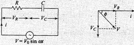
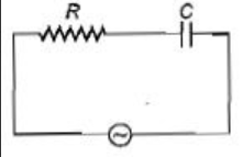
A series $R-C$ circuit is connected to an alternating voltage source. Consider two situation:
$(a)$ When capacitor is filled
$(b)$ When capacitor is mica filled
Current through resister is $i$ and voltage across capacitor is $V$ then:
AnswerFor series $C - R$ circuit, the impedance $\text{Z}=\sqrt{\text{R}^2+\text{X}^2_\text{C}}$ where $\text{X}_\text{C}=\frac{\text{i}}{\omega\text{C}}$ and current $\text{I}=\frac{\text{V}}{\text{Z}}$
When the capacitor is filled by mica, the capacitance will be increased.
If $C$ increases$, X_{C}$ decreases, so the current will increase and
hence voltage across resistance increases and voltage across capacitor decreases. thus$, V_a > V_{b}$
View full question & answer→Question 301 Mark
For a series LCR circuit the power loss at resonance is : -
Question 311 Mark
In an ideal parallel LC circuit, the capacitor is charged by connecting it to a D.C. source which is then disconnected. The current in the circuit.
Answer
- Oscillates instantaneously
Explanation:
In an LC circuit current oscillates between, maximum and minimum value. So, LC circuit needs oscillations (electrical). It occurs due to discharging and charging of capacitor and magnetisation and demagnetisation of inductor
View full question & answer→Question 321 Mark
The resonant frequency of an L - C circuit is.
Answer
- $\frac{1}{2\pi\sqrt{\text{LC}}}$
Explanation:
Resonance frequency f of an L - C circuit can be written as
Resonance frequency $\text{f}=\frac{1}{2\pi\sqrt{\text{LC}}}$ where L = inductance and C is capacitance. View full question & answer→Question 331 Mark
In an $\text{LCR}$ circuit, capacitance is changed from $C$ to $2C$. For the resonant frequency to remain unchanged, the inductance should be changed from $L$ to:
AnswerResonant frequency, $\text{f}_\text{r}=\frac{1}{2\pi\sqrt{\text{LC}}}$
As the frequency is unchanged so $f_r = f_r′$
$LC = L′C ′= L′(2C)$
$\text{L}=\frac{\text{L}}{2}$
View full question & answer→Question 341 Mark
Alternating current is flowing in inductance L and resistance R. The frequency of source is $\frac{\omega}{2\pi}$ Which of the following statement in correct:
Answer
- For low frequency the limiting value of impedance is L.
View full question & answer→Question 351 Mark
When an $AC$ voltage of $220V$ is applied to the capacitor $C$ :
AnswerIf the alternating voltage is applied to the capacitor, the plate connected to the positive terminal of the source will be at higher potential and the plate connected to the negative terminal of source will be at lower potential.
So the plates capacitor is charged.
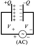
If $\text{V}=\text{V}_0\sin\omega\text{t},\text{Q}=\text{C V}_0\sin\omega\text{t}$ or we can say that $Q$ and emf are in pahse.
As $\text{P}=\text{V}_\text{rms}\text{I}_\text{rms}\cos\phi$ and in case of a capacitor, $\phi=\frac{\pi}{2}\text{P} = 0,$ or we can say that power delivered to the capacitor is zero.
$\Rightarrow P_{av} =$ power delivered $= 0.$ View full question & answer→Question 361 Mark
The resultant reactance in an $\text{L - C - R}$ circuit is.
AnswerReactance is the nonresistive component of impedance in an $AC$ circuit, arising from the effect of inductance or capacitance or both and causing the current to be out of phase with the electromotive force causing it.
Therefore, reactance of the $\text{L - C - R}$ circuit is $X_L - X_C.$
View full question & answer→Question 371 Mark
Current in the circuit is wattless, if.
AnswerCurrent in the circuit is wattless,
Because power $= i^2R,$ if $R = 0,$ then $P = 0.$
View full question & answer→Question 381 Mark
If a capacitor is connected to two different A.C. generators, then the value of capacitive reactance is:
Answer
- inversely proportional to frequency
Explanation:
$\text{X}_\text{C}=\frac{1}{\omega\text{c}}$
$\therefore\text{X}_\text{C}\propto\frac{1}{\omega}$ View full question & answer→Question 391 Mark
An inductive coil has resistance of $100\Omega$ When an ac signal of frequency $1000 Hz$ is fed to the coil, the applied voltage leads the current by $45^\circ C.$ What is the inductance of the coil?
Answer$\tan(45)=1\frac{\text{L}\omega}{\text{R}}$
$\text{L}=\frac{\text{R}}{\omega}=\frac{\text{R}}{(2\pi1000)}=.016\text{H}$
View full question & answer→Question 401 Mark
Statement A: With an increase in the frequency of AC supply inductive reactance increases.
Statement B: With an increase in the frequency of AC supply capacitive reactance increase.
Answer
- A is true but B is false
Explanation:
$\text{Z}_\text{L}=\text{WL}\ \ \ \text{Z}_\text{C}=\frac{1}{\text{WC}}$
$\text{w}\uparrow,\text{Z}_\text{L}\uparrow\text{Z}_\text{c}\downarrow$ View full question & answer→Question 411 Mark
If the phase difference between Alternating Voltage and Alternating Current is $\frac{\pi}{6}$ and the resistance in the circuit is $\sqrt{300}\Omega,$ then the impedance of the circuit will be.
Answer
- $20\Omega$
Explanation:
$\text{impedance}×\cos\theta = \text{resistance}$
$\text{impedance} = \frac{\text{resistance}}{\cos\theta}$
$=\frac{\sqrt{300}}{\frac{\cos\pi}{6}}$
$20\Omega$ View full question & answer→Question 421 Mark
If the value of C in a series RLC circuit is decreased, the resonant frequency.
Answer
- increases
Explanation:
Resonant frequency in the series RLC circuit $\text{v}_\text{r}=\frac{1}{2\pi\sqrt{\text{LC}}}$
$\Rightarrow\text{v}_\text{r}\propto\frac{1}{\sqrt{\text{C}}}$
Thus resonant frequency of the circuit increases if the value of C decreases. View full question & answer→Question 431 Mark
When the frequency of AC is doubled, the impedance of an LCR series circuit:
Question 441 Mark
The phase angle between current and voltage in a purely inductive circuit is:
Answer
- $\frac{\pi}{2}$
Explanation:
In the above image waveform of current and voltage in puerly inductive circuit with time is shown.
It is clear from the image that current lags voltage by 90°.
Hence phase angle between current and voltage in purely inductive circuit is $\frac{\pi}{2}$ View full question & answer→Question 451 Mark
An inductor of reactance $1\Omega$ and a resistor of $2\Omega$ are connected in series to the terminals of a $6V (rms)\ a.c.$ source. The power dissipated in the circuit is:
AnswerAccording to the problem$, X_L = 1Ω, R = 2Ω,$
$E_{rms} = 6V, P_{av} = ?$
Average power dissipated in the circuit
$\text{P}_\text{av}=\text{E}_\text{rms}\text{I}_\text{rms}\cos\phi \ .....(\text{i})$
$\text{I}_\text{rms}=\frac{\text{E}_\text{rms}}{\text{Z}}$
$\text{Z}=\sqrt{\text{R}^2+\text{X}^2_\text{L}}$
$=\sqrt{4+1}=\sqrt{5}$
$\text{I}_\text{rms}=\frac{6}{\sqrt{5}}\text{A}$
$\cos\phi=\frac{\text{R}}{\text{Z}}=\frac{2}{\sqrt{5}}$
$\text{P}_\text{av}=6\times\frac{6}{\sqrt{5}}\times\frac{2}{\sqrt{5}}\ \ [$from Eq. $(i)]$
$=\frac{72}{\sqrt{5}\sqrt{5}}=\frac{72}{5}=14.4\text{W}$
View full question & answer→Question 461 Mark
The instantaneous voltage through a device of impedence $20\Omega$ is $\text{e}=80\sin100\pi\text{t}.$ The effective value of the current is.
AnswerGiven equation, $\text{e}=80\sin100\pi\text{t}.(\text{i})$
Standard equation of instantaneous voltage given by $E = \text{e}_\text{m}\sin(\omega\text{t})......(\text{i})$
Compare $(i)$ and $(ii),$ we get $e_m = 80V$
where $e_m$ is the voltage amplitude.
Current amplitude $\text{I}_\text{m}=\frac{\text{e}_\text{m}}{\text{Z}}$ where $Z =$ impedence
$=\frac{80}{20}=4\text{A}$
$\text{I}_\text{r.m.s}=\frac{4}{\sqrt{2}}=\frac{4\sqrt{2}}{2}=2\sqrt{2}=2.828\text{A}$
View full question & answer→Question 471 Mark
In a circuit $L, C$ and $R$ are connected in series with an alternating voltage source of frequency $f$. The current leads the voltage by $45^\circ$ . The value of $C$ is.
AnswerHere $X_C - X_L = R$
$\Rightarrow\frac{1}{2\pi\text{f}}=(\text{R}+2\pi\text{fL})$
$\Rightarrow\text{C}=\frac{1}{2\pi\text{f}(2\pi\text{fL + R})}$
View full question & answer→Question 481 Mark
The capacitive reactance of $50\mu\text{F}$ capacitance at a frequency of $2 \times 10^3Hz$ will be$ ......... \Omega$
AnswerCapacitive reactance $=\frac{1}{\omega\text{c}}$
$=\frac{1}{2\pi\text{fc}}$
$=\frac{1}{2\pi2\times10^3\times50\times10^{-6}}$
$=\frac{5}{\pi}\Omega$
View full question & answer→Question 491 Mark
The impedance of a series L - C - R circuit in an AC circuit is.
Answer
- $\text{None of these}$
Explanation:
$\text{Z}=\sqrt{\text{R}^2+(\text{X}_\text{L}-\text{X}_\text{C})^2}$ View full question & answer→Question 501 Mark
Alternating current is one which changes in its:
Answer
- magnitude and direction both
Explanation:
An alternating current (AC) is an electric current whose magnitude and direction vary, unlike direct current, whose direction remains constant.
The usual waveform of an AC power circuit is a sine wave, because this leads to the most efficient transmission of energy. The sine wave oscillates periodically between positive and negative direction.
View full question & answer→Question 511 Mark
A steady potential difference of 100V produces heat at a constant rate in a resistor. The alternating voltage which will produce half the heating effect in the same resister will be.
Answer
- 100V
Explanation:
The power supplied to the resistor by DC source $=\frac{\text{V}^2_\text{dc}}{\text{R}}$
Energy given by AC source $\int_{0}^{\text{T}}=\frac{\text{V}^2_0}{\text{R}}\text{dt}$
Hence, $\int_{0}^{\text{T}}=\frac{\text{V}^2_0\sin^2\omega\text{t}}{\text{R}}\text{dt}=\frac{1}{2}\times\frac{\text{V}^2_\text{dc}\text{T}}{\text{R}}$
$\Rightarrow\text{V}_0=\text{V}_\text{dc}=100\text{V}$ View full question & answer→Question 521 Mark
A 220V main supply is connected to a resistance of $100\text{k}\Omega$ The effective current is?
Answer
- $2.2\text{mA}$
Explanation:
Effective current is the rms value. Here, 220V is the labelled value of AC which is also the rms value. Hence,
$\text{I}_\text{rms}=\frac{\text{E}_\text{rms}}{\text{R}}$
$\text{I}_\text{rms}=\frac{220}{100\times10^3}$
$\text{I}_\text{rms}=2.2{\text{mA}}$ View full question & answer→Question 531 Mark
An inductance and resistance are connected in series with an A.C circuit. In this circuit.
Answer
- the current and P.d across the resistance lags behind the P.d. across the inductance by angle $\frac{\pi}{2}$
Explanation:
This is very fundamental. If we apply separate voltages across resistance and inductor, then in resistance, current and voltage both are in same phase whereas in inductor, current across it lags p.d across it by $\frac{\pi}{2}.$
Now, when we apply voltage across inductor and resistance connencted in series then current through both of them will be same because of KCL. therefore voltage across resistor will be in same phase with current whereas voltage across inductor will lead the current across it by $\frac{\pi}{2}.$ therefore current and voltage across resistor lags voltage across inductor by $\frac{\pi}{2}$ View full question & answer→Question 541 Mark
A constant current of 2.8A exists in a resistor. The rms current is:
Answer
- 2.8A.
Explanation:
A constant current exists in a resistor is rms current it is equal to 2.8Amp.
View full question & answer→Question 551 Mark
For watt$-$less power in an $AC$ circuit the phase angle between the current and voltage is.
AnswerWatt$-$less power in an $AC$ circuit is basically power supposed to be generated by inductive and capacitive reactance and since they are not resistor they generate any heat, and these power wasted is called watt$-$less power and its phase angle is always $90^\circ$ as it has only capacitor and inductor.
View full question & answer→Question 561 Mark
In an AC circuit, the impedance is 3 times the reactance, then the phase angle is.
Answer
- none of these
Explanation:
$\sin\phi=\frac{\text{X}}{\text{Z}}=\frac{1}{\sqrt{3}}$
$\therefore\phi=\sin^{-1}\Big(\frac{1}{\sqrt{3}}\Big)$ View full question & answer→Question 571 Mark
An AC source is rated 220V, 50Hz. The average voltage is calculated in a time interval of 0.01s, It:
Answer
- May be zero.
Explanation:
- $\text{V}=\text{V}_0\sin\omega\text{t}$
$\omega=2\pi\text{f}=2\times3.14\times50$
$\omega=314$
$\text{V}_\text{avg}=\frac{\int\limits_0^{0.01}\text{V}\text{dt}}{\int\limits_0^{0.01}\text{dt}}$
$=\text{V}_0\Big(\frac{1\cos\omega\text{t}}{\omega}\Big)_0^{0.01}$
$=\frac{\text{V}_0}{\omega\times0.01}\big(1-\cos\omega(0.1)\big)$
$=\frac{\text{V}_0}{314\times0.01}\big(1-\cos(314\times0.01)\big)$
$=\frac{\text{V}_0}{3.14}\big(1-\cos(314)\big)$
$=\frac{\text{V}_0}{3.14}\big(1-\cos\pi\big)$
$=\frac{2\text{V}_0}{\pi}=140.127\text{volt}$
-
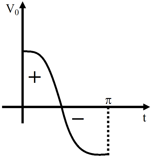
if $\text{V}=\text{V}_0\cos\omega\text{t}$
$\text{V}_\text{avg}=\frac{\int\text{V d}\rho}{\int\text{dt}}=0$ View full question & answer→Question 581 Mark
The frequency of A.C mains in India is.
Answer
- 50Hz
Explanation:
In India, the AC mains supply is referred to as single-phase alternating current and corresponds to a voltage of 230 V at a frequency of 50Hz, similar to most European countries. Whereas in the USA, AC mains supply uses 60Hz.
View full question & answer→Question 591 Mark
Which of the following combinations should be selected for better tuning of an LCR circuit used for communication?
Answer
- R = 15Ω, L = 3.5 H, C = 30μF.
Solution:
Quality factor (Q) of an L-C-R circuit is given by, $\text{Q}=\frac{1}{\text{R}}\sqrt{\frac{\text{L}}{\text{C}}}$
Tuning of an L-C-R circuit depends on quality factor of the circuit. Tuning will be better when quality factor of the circuit is high.
As, quality factor (Q) of an L-C-R circuit is given by, $\text{Q}=\frac{1}{\text{R}}\sqrt{\frac{\text{L}}{\text{C}}}$
For Q to be high, R should be low, L should be high and C should be low, Therefore option (c) is most apporopriate. View full question & answer→Question 601 Mark
In an ac circuit, the potential differences across an inductance and resistance joined in series are, respectively, 16V and 20V. The total potential difference across the circuit is.
Answer
- 25.6V
Explanation:
In phasor, $\text{V}_\text{R}=20\angle0;\text{V}_\text{L}=16\angle(-90)$
Total potential difference is $=\text{V}_\text{R}+\text{V}_\text{L}=25.6\angle(-38.66)$
Magnitude of total potential difference = 25.6V View full question & answer→Question 611 Mark
The capacitor of an oscillatory circuit of negligible resistance is enclosed in a evacuated container. The frequency of the circuit is 150 kHZ and when the container is filled with a gas, the frequency changes by 100 HZ. The dielectric constant of the gas.
Answer
- 1.0012
Explantion:
We know frequency is given by:
$\text{n}_1=\frac{1}{2\pi\sqrt{\text{LC}_1}}$
And
$\text{n}_2=\frac{1}{2\pi\sqrt{\text{LKC}_1}}$
Thus we get the ratio of frequencies as
$\frac{\text{n}_1}{\text{n}_2}=\frac{150000}{149900}=\sqrt{\text{k}}$
Solving the above equation we get, $\text{K}\approx1.0012$ View full question & answer→Question 621 Mark
A resistor and an inductor are connected to an ac supply of $120V$ and $50\ Hz$. The current in the circuit is $3A$. If the power consumed in the circuit is $108W,$ then the resistance in the circuit is.
Answer$I_{rms} =$ currentincircuit $= 3A$
$\text{p}=108\text{W}=\text{I}_\text{ems}^2\text{R}=3^2\text{R}$
$\text{R}=\frac{108}{9}=12\Omega$
View full question & answer→Question 631 Mark
The phase difference between alternating emf and current in a purely capacitive circuit will be.
Answer
- $-\frac{\pi}{2}$
Explanation:
In a purely capacitive circuit, current leads the voltage by $-\frac{\pi}{2}$ View full question & answer→Question 641 Mark
What is the range of the characteristic impedance of a coaxial cable?
Answer
- $\text{Between }50\Omega \text{ to } 70\Omega$
Explanation:
Characteristic impedance of a coaxial cable is $\text{Between }50\Omega \text{ to } 70\Omega$ View full question & answer→Question 651 Mark
An inductor has a resistance R and inductance L. It is connected to an AC source of emf Ev and angular frequency ω; then the current Iv in the circuit is:
Answer
- $\frac{\text{E}_\text{v}}{\sqrt{\text{R}^2+\omega^2\text{L}^2}}$
Explanation:
The impedance in R-L circuit is
$\text{Z}=\sqrt{\text{R}^2+{\text{X}^2_\text{L}}}=\sqrt{\text{R}^2+{(\omega\text{L})^2}}$
The current $\text{I}_\text{V}=\frac{\text{E}_\text{V}}{\text{Z}}$
$\frac{\text{E}_\text{v}}{\sqrt{\text{R}^2+\omega^2\text{L}^2}}$ View full question & answer→Question 661 Mark
In R - L - C series circuit, the potential differences across each element is 20V. Now the value of the resistance alone is doubled, then P.D. across R, L and C respectively.
Answer
- 20V, 10V, 10V
Explanation:
Circuit is at resonance (VL = VC)
$\therefore$ circuit is purely resistance
Resistance is doubled, current in the circuit is half the initial value
$\therefore$ New current $\text{I′}=\frac{\text{I}}{2}$
$\therefore$ VR = 20V (equal to applied voltage earlier)
VL = 10V
VC = 10V View full question & answer→Question 671 Mark
In an AC series circuit, the instantaneous current is zero when the instantaneous voltage is maximum. Connected to the source may be a:
Answer
- Pure inductor.
- Pure capacitor.
- Combination of an inductor and a capacitor.
Explanation:
Instantaneous current is zero when the intantaneous voltage is maximum.
Mean resistance = 0.
View full question & answer→Question 681 Mark
If the frequency of an A.C is made 4 times of its initial value, the inductive reactance will.
Answer
- be 4 times
Explanation:
inductive reactance $=2\pi\text{fL}$
therefore when f is made 4 times, inductive reactance also becomes 4 times View full question & answer→Question 691 Mark
In an AC circuit containing only capacitance, the current:
Answer
- leads the voltage by 90
Explanation:
Current leads by 90°.
View full question & answer→Question 701 Mark
If the rms current in a $50\ Hz$ ac circuit is $5A,$ the value of the current $\frac{1}{300}$ seconds after its value becomes zero is,
AnswerKey concept: Equation for $i$ and $V$ : Alternating current or voltage varying as sine function can be written as
$\text{i}=\text{i}_0\ \sin\omega\text{t}=\text{i}_0\ \sin2\pi\text{v t}=\text{i}_0\sin\frac{2\pi}{\text{T}}\text{t}$
and $\text{V}=\text{V}_0\ \sin\omega\text{t}=\text{V}_0\ \sin2\pi\text{v t}=\text{V}_0\sin\frac{2\pi}{\text{T}}\text{t}$
where $i$ and $V$ are instantaneous values of current and voltage,
$i_0$ and $V_0$ are peak values of current and voltage
$\omega$ = Angular frequency in $\frac{\text{red}}{\text{sec}}, v =$ Frequency in $Hz$ and $T =$ time period
Accoeding to the problem$, f = 50\ Hz, I_{rms} = 5A$
$\text{t}=\frac{\text{I}}{300}\text{s}$
$\text{I}_0=$ Peak value $=\sqrt{2}(\text{I}_\text{rms})=5\sqrt{2}$
$=5\sqrt{2}\text{A}$From, $\text{I}=\text{I}_0\sin\omega\text{t}=5\sqrt{2}\sin2\pi\text{vt}=5\sqrt{2}\sin2\pi\times50\times\frac{1}{300}$
$=5\sqrt{2}\sin\frac{\pi}{3}=5\sqrt{2}\times\frac{\sqrt{3}}{2}=5\sqrt{\frac{3}{2}}\text{A}$ View full question & answer→Question 711 Mark
In a series $\text{LCR}$ circuit, resonance occurring at $105\ Hz.$ At that time, the potential difference across the $100$ resistance is $40V$ while the potential difference across the pure inductor is $30v.$ The inductance $L$ of the inductor is equal to.
AnswerIn a series $\text{LCR}$ circuit, resonance occurring at $105\ Hz.$
At that time, the potential difference across the $100$ resistance is $40V$ while the potential difference
across the pure inductor is $30V.$
The inductance $L$ of the inductor is equal to
Current$(i) =\frac{\text{V}_\text{r}}{\text{R}}=\frac{100}{40}=2.5\text{A}$
the inductor value is $V_L = i \times (wL)$
$\text{L}=\frac{30}{2.5\times2\times\pi1\times105}$
$=1.2\times10^{-4}\text{H}$
View full question & answer→Question 721 Mark
A 5cm long solenoid having 10 ohm resistance and 5mH inductance is joined to a 10V battery. At steady state, the current through the solenoid (in ampere) will be.
Answer
- 1
Explanation:
At steady state inductor behave like short circuit.
$\text{i}=\frac{\text{v}}{\text{r}}=\frac{10}{10}=1\text{A}$ View full question & answer→Question 731 Mark
The magnetic field energy in an inductor changes from maximum value to minimum value in 5.0ms when connected to an AC source. The frequency of the source:
Answer
- 50Hz.
Explanation:
Frequency of the source is remain constant = 50Hz.
View full question & answer→Question 741 Mark
Inductive reactance of a coil is expressed in.
Answer
- Ohm
Explanation:
Inductive reactance or capacitive reactance are the impedance of an AC circuit which has the units of ohms.
View full question & answer→Question 751 Mark
An LCR series circuit with $100\Omega$ resistance is connected to an ac source of 200V and of frequency of $\frac{300 \text{rad}}{\text{s}}$. When only the capacitance is removed, the current lags behind the voltage by 600. When only the inductance is removed, the current leads the voltage by 60° the current through the circuit is:
Answer
- 2 A
Explanation:
Since current lead and lag are same So, circuit is in resonance, so, circuit is purely resistive circuit.
So, $\text{i}=\frac{\text{V}}{\text{R}}$
$=\frac{200}{100}$
$=2\text{A}$ View full question & answer→Question 761 Mark
A capacitor acts as an infinite resistance for.
Answer
- DC
Explanation:
Capacitors contain at least two electrical conductors separated by a dielectric/ insulator and is used to store energy electrostatically between the conductors. It acts like an open circuit and hence acts like an infinite resistance for DC currents.
View full question & answer→Question 771 Mark
An inductor coil of some resistance is connected to an AC source. Which of the following quantities have zero average value over a cycle?
Answer
- Current.
- Induced emf in the inductor.
Explanation:
$\text{I}=\text{I}_0\sin\omega\text{t}$
Average value of current over a cycle = 0
$\text{V}=\text{V}_0\cos\omega\text{t}$
$=\text{V}_0\sin\bigg(\omega\text{t}+{\frac{\pi}{2}}\bigg)$
Average value of induced emf in inductor over a cycle = 0. View full question & answer→Question 781 Mark
In a series L - C - R circuit, current in the circuit is 11A when the applied voltage is 220V. Voltage across the capacitor is 200V. If value of resistor $20\Omega$ then the voltage across the unknown inductor is.
Answer
- 200V
Explanation:
The given LCR circuit is in resonance. Inductive reactance magnitude XL increases as frequency increases while capacitive reactance magnitude XC decreases with the increase in frequency.
At one particular frequency, these two reactances are equal in magnitude but opposite in sign; that frequency is called the resonant frequency fO for the given circuit. Hence, at resonance:
XL = XC
So the voltage across rthe unknown inductor is 200V as same as the voltage across the capacitor.
View full question & answer→Question 791 Mark
An LCR circuit has L = 10 mH, $\text{R}=3\Omega$ and $\text{C}=1\mu\text{ F}$ connected in series to a source of $15\cos\omega\text{t}$ volt. The current amplitude at a frequency that is 10% lower than the resonant frequency is:
Answer
- 0.7A
Explanation:
Resonant frequency, $\text{w}_\text{o}=\frac{1}{\sqrt{\text{LC}}}=\frac{1}{\sqrt{(10\times10^{-3})(10^{-6})}}=\frac{10^4\text{rad}}{\text{s}}$
New frequency $\omega=(0.9)\omega_\text{o}=9\times\frac{10^3\text{rad}}{\text{s}}$
We have new $\text{X}_\text{L}=\omega\text{L}=9\times10^3\times10\times10^{-3}=90\Omega\text{ and}\text{ X}_\text{C}=\frac{1}{\omega\text{C}}=111.11\text{ohm.}$
Thus we calculate new Z as
$\sqrt{3^2+[90-111.11]^2}$
$=21.32\Omega$
Current amplitude $=\frac{\text{V}_\text{o}}{\text{Z}}=\frac{15}{21.32}=0.7\text{A}$ View full question & answer→Question 801 Mark
At low frequency a condenser offers:
Answer
- high impedance
Explanation
$\text{Z}=\frac{1}{\text{WC}}$
$\text{W}\downarrow\text{Z}\uparrow$ View full question & answer→Question 811 Mark
An A.C. circuit containing only capacitance, the current:
Answer
- Leads the voltage by 90°
Explanation:
In an a.c. circuit containing resistance onIy voltage & current remain in the same phase. If circuit contains inductance only, voltage remains ahead of current by phase difference of 90°. If circuit contains capacitance only, current remains ahead of voltage by a phase difference of 90°.
View full question & answer→Question 821 Mark
In an alternating current circuit consisting of elements in series, the current increases on increasing the frequency of supply. Which of the following elements are likely to constitute the circuit?
AnswerResistor and a capacitor
Only a capacitor.
- This is the similar problem as we discussed above. In this problem, the current increases on increasing the frequency of supply.
- Hence, the reactance of the circuit must be decreased as increase in frequency.
- So, one element that must be connected is capacitor.
- We can also connect a resistor in series.
For a capacitive circuit,
$\text{X}_\text{C}=\frac{1}{\omega\text{C}}=\frac{1}{2\pi\text{fC}}$
When frequency increases $, X_C$ decreases.
- Hence current in the circuit increases.
Importance point: Resistive, Capacitive Circuit $(RC-$ Circuit$)$
$V_R = iR,$
$V_C = iX_C,$
$V_R = iR$
- Applied voltage: $\text{V}=\sqrt{\text{V}^2_\text{R}+\text{V}^2_\text{C}}$
- Impedance: $\text{Z}=\sqrt{\text{R}^2+\text{X}^2_\text{C}}=\sqrt{\text{R}^2+\Big(\frac{1}{\omega\text{C}}\Big)^2}$
- Current: $\text{i}=\text{i}_0\sin(\omega\text{t}+\phi)$
- Peak current: $\text{i}_0=\frac{\text{V}_0}{\text{Z}}=\frac{\text{V}_0}{\sqrt{\text{R}^2+\text{X}^2_\text{C}}}=\frac{\text{V}_0}{\sqrt{\text{R}^2+\frac{1}{4\pi^2\text{v}^2\text{C}^2}}}$
- Phase difference: $\phi=\tan^{-1}\frac{\text{X}_\text{C}}{\text{R}}=\tan^{-1}\frac{1}{\omega\text{CR}}$
- Power factor: $\cos\phi=\frac{\text{R}}{\sqrt{\text{R}^2+\text{X}^2_\text{C}}}$
- Leading quantity: Current.
View full question & answer→Question 831 Mark
What is the value of inductance L for which the current is a maximum in a series LCR circuit with $\text{C}=10\mu\text{F}$ and $\omega=1000_\text{s}^{-1}$?
View full question & answer→Question 841 Mark
In an oscillating system, a restoring force is a must. In an L-C circuit, the restoring force is provided by a/ an.
Question 851 Mark
A resistor and a capacitor are in series across a 20V ac source. Circuit impedance is $4.33\text{k}\Omega$ Current flow in the circuit is.
Answer
- 4.6mA
Explanation:
Voltage of the source V = 20 volts
$\text{Z}=4.33\text{k}\Omega=4.33\times10^3\Omega$
Thus current in the circuit $\text{I}=\frac{\text{V}}{\text{Z}}$
$\therefore\text{I}=\frac{20}{4.33\times10^3}=4.6\times10^{-3}\text{A}$
$\Rightarrow\text{I}=4.6\text{mA}$ View full question & answer→Question 861 Mark
A mixer of $100\Omega$ resistance is connected to an A.C. source of 200V and 50 cycles/ sec. The value of average potential difference across the mixer will be:
Answer
- zero
Explanation:
We need to find the average potential difference across the mixer. Here by average we mean average over a long period of time. As we know in one complete cycle, average voltage across the mixer is zero. (In one complete cycle current changes the direction and net voltage across a resistor is zero).
So when in one complete cycle voltage drop across the resistor is zero, then the average voltage drop across the resistor (mixer) is zero.
View full question & answer→Question 871 Mark
If we increase the driving frequency in a circuit with a purely resistive load, then amplitude VR.
Answer
- remain in the same
Explanation:
We know that VR does not depend on driving frequency in a purely resistive circuit. So, If we increase the driving frequency in a circuit with a purely resistive load, then amplitude remain in the same.
View full question & answer→Question 881 Mark
The square root of the product of inductance and capacitance has dimensions of.
Answer
- time
Explanation:
$\text{f}=\frac{1}{\sqrt{\text{LC}}}$
$\text{or}{\sqrt{\text{LC}}}=\text{T}$ View full question & answer→Question 891 Mark
An inductor, a resistor and a capacitor are joined in series with an AC source. As the frequency of the source is slightly increased from a very low value, the reactance.
Answer
- of the inductor increases
View full question & answer→Question 901 Mark
For an LCR circuit, the power transferred from the driving source to the driven oscillator is $\text{P}=\text{FZ}\cos\phi$.
Answer
- Here, the power factor $\cos\phi\geq0,\text{P}\geq0$.
- The driving force can give no energy to the oscillator (P = 0) in some cases.
- The driving force cannot syphon out (P < 0) the energy out of oscillator.
Solution:
Key Concept: Power Factor.
- It may be defined as cosine of the angle of lag of lead (i.e., $\cos\phi$).
- It is also defined as the radio of resistance and impedange $\Big(\text{i.e.,} \frac{\text{R}}{\text{Z}}\Big)$.
- $\text{The radio}=\frac{\text{True power}}{\text{Apparent power}}=\frac{\text{W}}{\text{VA}}=\frac{\text{kW}}{\text{kVA}}=\cos\phi$
In the given problem power transferred,
$\text{P}=\text{I}^2\text{Z}\cos\phi$
where I is the current, Z = Impedance and $\cos\phi$ is power factor
- As power factor, $\cos\phi=\frac{\text{R}}{\text{Z}}$
where R > 0 and Z > 0
$\Rightarrow\ \cos\phi>0\Rightarrow\ \text{P}>0$
- When $\phi=\frac{\pi}{2}$ (in case of L of C), P = 0.
- From (a), it is clear that P < 0 is not possible.
View full question & answer→Question 911 Mark
The equation of an alternating voltage is E = 220 E = 220.Then the impedance of the circuit is:
Answer
- 22 ohm
Explanation:
Our experts are building a solution for this.
View full question & answer→Question 921 Mark
A series AC circuit has a resistance of $4\Omega$ and a reactance of $3\Omega$. The impedance of the circuit is.
Answer
- $5\Omega$
Explanation:
Impedance(Z) $=\sqrt{\text{R}^2+\text{X}^2}$
where, R = resistance
X = reactance
Given $\text{R}=4\Omega\text{ and }\text{X}=3\Omega$
Substitute values back in equation
$\text{Z}=\sqrt{4^2+3^2}$
$\text{Z}=5\Omega$ View full question & answer→Question 931 Mark
The AC voltage across a resistance can be measured using:
Answer
- A hot-wire voltmeter.
Explanation:
The AC voltae across a resustance can be measured using a hot-wore volmeter.
View full question & answer→Question 941 Mark
In non-resonant circuit, what will be the nature of the circuit for frequencies higher than the resonant frequency?
Answer
- Inductive
Explanation:
At resonant frequency
$\text{X}_\text{L}=\text{X}_\text{C}=\Big(\omega\text{L}=\frac{1}{\omega\text{C}}\Big)$
At frequencies higher than resonance frequencies
$\text{X}_\text{L}>\text{X}_\text{C}$
i.e., behaviour is inductive. View full question & answer→Question 951 Mark
An $AC$ source producing emf $\epsilon=\epsilon_{0}\Big[\cos\big(100\pi\text{s}^{-1}\big)\text{t}+\cos\big(500\pi\text{s}^{-1}\big)\text{t}\Big]$ is connected in series with a capacitor and a resistor. The steady-state current in the circuit is found to be $\text{i}=\text{i}_1\cos\Big[\big(100\pi\text{s}^{-1}\big)\text{t}+\phi_1\Big]+\text{i}_2\cos\Big[\big(500\pi\text{s}^{-1}\big)\text{t}+\phi_2\Big].$
Answer$\text{Q}=\text{C}\epsilon=\epsilon_{0}\text{C}\Big[\cos\big(100\pi\text{s}^{-1}\big)\text{t}+\cos\big(500\pi\text{s}^{-1}\big)\text{t}\Big]$
$\text{i}=\frac{\text{dQ}}{\text{dt}}$
$\text{Q}=\text{C}\epsilon=\epsilon_{0}\text{C}\Big[\cos\big(100\pi\text{s}^{-1}\big)\text{t}+\cos\big(500\pi\text{s}^{-1}\big)\text{t}\Big]$
$\epsilon_0\text{C}\times100\pi\Big[\sin\big(100\pi\text{s}^{-1}\big)\text{t}\Big]$
$+\epsilon_0\text{C}\times500\pi\Big[\sin\big(500\pi\text{s}^{-1}\big)\text{t}\Big]$
$=100\text{C}\pi\epsilon_0\cos\Big[\big(100\pi\text{s}^{-1}\big)\text{t}+\phi_1\Big]$
$+500\text{C}\pi\epsilon_0\cos\Big[\big(500\pi\text{s}^{-1}\big)\text{t}+\phi_2\Big]$
$\text{i}_1=100\pi\epsilon_0\text{C}$ and $\text{i}_2=500\pi\epsilon_0\text{C}$
$\text{i}_2>\text{i}_1$
View full question & answer→Question 961 Mark
Electrical energy is transmitted over large distances at high alternating voltages. Which of the following statements is $($are$)$ correct?
Answer
- For a given power level, there is a lower current.
- Lower current implies less power loss.
- It is easy to reduce the voltage at the receiving end using step-down transformers.
Solution:
Key Concept: Power loss due to transmisssion lines having resistance $(R)$ and $I_{rms}$ current flowing in the circuit is $I^2_{rms} R.$
The power is to be transmitted over the large distances ar high alternating voltages, so current flowing through the wires will be low because of given power $(P).$
For a given power level, we find that
$P = E_{rms}I_{rms} (I_{rms}$ is low when $E_{rms} is high)$
Powor loss $= I^2_{rms} R = low ( \because I_{rms} is low)$
Now at the receiving end high voltage is reduced by using step-down transformers. View full question & answer→Question 971 Mark
If the frequency of an alternating e.m.f. is f in L-C-R circuit, then the value of impedance Z as log(frequency) increases:
Answer
- decreases and when it becomes minimum, equal to the resistance then it will start increasing
Explanation:

If the frequency of an alternating e.m.f. is f in L-C-R circuit, then the value of impedance Z decreases and when it becomes minimum, equal to the resistance then it will start increasing as log(frequency) increases:
View full question & answer→Question 981 Mark
The unit of susceptance is.
AnswerSusceptance is the imaginary part of admittance.
The admittance is the inverse of impedance.
Unit of admittance is ohm. Unit of admittance is $ohm^{-1}$ or siemens.
Unit of susceptance is same as of admittance.
View full question & answer→Question 991 Mark
If the values of L, C and R in a series L - C - R circuit are $100\text{mH},100\mu\text{F}$ and $100\Omega$ respectively then the value of resonant frequency will be.
Answer
- $\frac{10}{2\pi}\text{Hz}$
Explanation:
Resonant frequency $=\frac{1}{2\pi\sqrt{\text{LC}}}$
$=\frac{1}{2\pi\sqrt{10^{-6}}}$
$=\frac{10}{2\pi}\text{Hz}$ View full question & answer→Question 1001 Mark
If in a series $L - C - R$ ac circuit, the voltages across $L, C$ and $R$ are $V_1, V_{2}$ and $V_3$ respectively, then the voltage of the source is always.
AnswerThe voltages across different elements in $AC$ circuit add vectorially.
The voltages across inductor and capacitor are out of phase and at $90^\circ$ to that across resistor.
Hence net voltage across source $=\sqrt{(\text{V}_1-\text{V}_2)+\text{V}^2_3}.$
View full question & answer→Question 1011 Mark
A coil of self-inductance L is connected in series with a bulb B and an AC source. Brightness of the bulb decreases when.
Answer
- An iron rod is inserted in the coil
Explanation:
As the iron rod is inserted, the magnetic field inside the coil magnetizes the iron increasing the magnetic field inside it. Hence. the inductance of the coil increases. Consequently, the inductive reactance of the coil increases. As a result, a larger fraction of the applied AC voltage appears across the lnductor, leaving less voltage across the bulb.Therefore' the brightness of the light bulb decreases.
View full question & answer→Question 1021 Mark
A coil of $10\text{mH}$ and $10\Omega$ resistance is connected in parallel to a capacitance of $0.1\mu\text{F}$ The impedance of the.
View full question & answer→Question 1031 Mark
A solenoid of length 10cm, diameter 1cm, number of turns 500 with relative permeability of the core 2000, is connected to an ac source of frequency 50 Hz. Then, the reactance is.
Answer
- $155\Omega$
Explanation:
Inductance of the solenoid $=\text{L}=\frac{\mu\text{N}^2\text{A}}{1}=0.493\text{H}$
reactance of this solenoid $=\text{L}\omega=\text{L}2\pi\text{f}=155\Omega$ View full question & answer→Question 1041 Mark
When the rms voltages $V_L, V_C$ and $V_{R}$ are measured respectively across the inductor $L,$ the capacitor $C$ and the resistor $R$ in a series $\text{LCR}$ circuit connected to an $AC$ source, it is found that the ratio $V_L : V_C : V_{R} = 1 : 2 : 3.$ If the rms voltage of the $AC$ source is $100 V,$ then $V_R$ is close to:
View full question & answer→Question 1051 Mark
An a.c. supply of 100 volts is applied to a capacitor of capacitance 20 μ F. If the current in the circuit is 0.628 A, the frequency of a.c. must be.
Answer
- 50 Hz
Explanation:
$\text{Y}=100\text{V, C}=2\mu\text{F}=20\times10^{-6}$
$\text{I}=0.628\text{A,v}=?$
$\text{X}_\text{C}=\frac{\text{V}}{\text{I}}=\frac{100}{0.628}$
$\Rightarrow\frac{1}{2\pi\text{vC}}=\frac{100}{0.628}$
$\text{v}=\frac{0.628}{100\times2\pi\text{C}}$
$=50\text{ Hz}$ View full question & answer→Question 1061 Mark
A sinusoidal voltage $\text{V}=200\sin314\text{t}$ is applied to a $10\Omega$ resistor. Find the peak voltage.
AnswerGeneral sinusoidal voltage variation is given by:
$\text{V}=\text{V}_0\sin(\omega\text{t})$
Here, in this equation $V_0$ is peak voltage.
So, on comparing both equation we get:
$\text{V}_0=200\text{V},\omega=314$
View full question & answer→Question 1071 Mark
The capacitance in an oscillatory LC circuit is increased by 1%. The change in inductance required to restore its frequency of oscillation is to.
Question 1081 Mark
The peak voltage in a 220V AC source is:
Answer
- About 310V.
Explanation:
$\text{V}_\text{rms}=220\text{V}$
$\text{V}_\text{p}=\sqrt{2}\times\text{V}_\text{rms}$
$=220\times1.414=311\text{volt}$ View full question & answer→Question 1091 Mark
An amplitude modulated (AM) radio operates at 550kHz to 1650kHz. If L is fixed and C is varied for tuning then minimum and maximum value of C is.
Answer
- C, 9C
Explanation:
$\frac{\text{f}_\text{max}}{\text{f}_\text{max}}=3$
$\therefore\frac{\sqrt{\text{LC}_\text{max}}}{\sqrt{\text{LC}_\text{min}}}=3$
$\frac{\text{C}_\text{max}}{\text{C}_\text{min}}=9$
${\text{C}_\text{min}}=\text{C}$
$\therefore{\text{C}_\text{max}}=\text{9C}$ View full question & answer→Question 1101 Mark
When the frequency of the source voltage decreases, the impedance of a parallel RC circuit.
Answer
- increases
Explanation:
When the frequency of the source voltage decreases, the impedance of a parallel RC circuit will increase.
View full question & answer→Question 1111 Mark
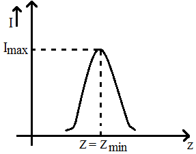
As the frequency of an ac circuit increases, the current first increases and then decreases. What combination of circuit elements is most likely to comprise the circuit?
Answer
- Inductor and capacitor.
- Resistor, inductor and capacitor.
Compare the given circuit by predicting the variation in their reactances with frequency.
So, that then we can decide the elements.
Reactance of an inductor of inductance $L$ is $\text{X}_\text{L}=2\pi\text{vL}$, where v is the frequency of the $AC$ circuit.
$X_c =$ Reactance of the capacitive circuit
$=\frac{1}{2\pi\text{fC}}$
With an increase in frequency in $(f)$ of an $AC$ circuit, $R$ remains constant, inductive reactance $(X_L)$ increases and capacitive reactance $(X_C)$ decreases.
For an $\text{L-C-R}$ circuit,
$Z-$ Impedance of the circuit,
$=\sqrt{\text{R}^2+(\text{X}_\text{L}-\text{X}_\text{C})^2}$
$=\sqrt{\text{R}^2+\bigg(2\pi\text{vL}-\frac{1}{2\pi\text{vC}}\bigg)^2}$
As frequency $(v)$ increases, $Z$ decreases and at certain value of the frequency known as resonant frequency $(v_0),$ impedance $Z$ is minimum that is $Z_{min} = R$ current varies inversely with impedance and at $Z_{min}$ current is maximum. View full question & answer→Question 1121 Mark
The angular frequency of an AC source is $\frac{10\text{radian}}{\text{sec}}$ The reactance of $1\mu\text{F}$ capacitor will be.
Answer
- $10^5\Omega$
Explanation:
$\text{Reactance}=\frac{1}{\text{C}\omega}\Omega$
$=\frac{1}{10^{-6}\times10}=\frac{1}{10^{-5}}$
$=10^5\Omega$ View full question & answer→Question 1131 Mark
In an A.C. circuit the potential difference across an inductance and resistance joined in series are respectively 16V and 20V. The total potential difference across the circuit is.
Answer
- 25.6V
Explanation:
Potential difference across the circuit
$\text{V}=\sqrt{\text{V}^2_\text{R}+\text{V}^2_\text{L}}=\sqrt{20^2+16^2}=\sqrt{656}=25.6\text{V}$ View full question & answer→Question 1141 Mark
The simplest type of AC voltage or current is the one which.
Answer
- Varies sinusoidally
Explanation:
AC voltage or current can be of any form, but the simplest type is a sine wave because any periodic wave can be represented as a combination of sine waves.
View full question & answer→Question 1151 Mark
Answer
- Partition function
Explanation:
Z- Atomic number we study in modern physics
Z- impedance we study in alternating current
Z-zeta potential
View full question & answer→Question 1161 Mark
Answer
- In AC circuits only.
Explanation:
Transformers are used in AC circuits only.
View full question & answer→Question 1171 Mark
In a series $\text{RLC}$ circuit that is operating above the resonant frequency, the current.
AnswerCapacitive reactance is given by. $\text{X}_\text{C}=\frac{1}{\text{wC}}$
Inductive reactance is given by $\text{X}_\text{L}={\text{wL}}$
At resonance, $\text{X}_\text{L}={\text{X}_\text{C}}\Rightarrow \text{w}\text{L}=\frac{1}{\text{wC}}$
But a frequency higher than resonance frequency, $X_L > X_C$
So the circuit behaves as a inductive circuit at a frequency higher that resonant frequency and the current lags behind the voltage in an inductive circuit.
View full question & answer→Question 1181 Mark
In a pure capacitive A.C circuit current and voltage differ in phase by.
Answer
- 90°
Explanation:
$\text{i}=\text{i}_\text{o}\sin(\omega\text{t}+\frac{\pi}{2})$
current leads voltage by $\frac{\pi}{2}$ i.e., current and voltage differ in phase by 90° View full question & answer→Question 1191 Mark
An AC source rated 100V (rms) supplies a current of 10A (rms) to a circuit. The average power delivered by the source:
Answer
- May be 1000W.
- May be less than 1000W.
Explanation:
Average power $\text{P}_\text{av}=\text{V}_\text{rms}\text{I}_\text{rms}\cos\phi$
$=100\times10\cos\phi$
$\text{P}_\text{av}=1000\cos\phi$
$\therefore\ \cos\phi$ lies "0 to 1".
$\Rightarrow\ 0\leq\text{P}_\text{av}\leq1000.$ View full question & answer→Question 1201 Mark
Voltage across each elements of a series $\text{LCR}$ circuit are given by $V_{L} = 60V, VC = 20V, V_R = 30V$ Find out source voltage.
Answer$\text{V}=\sqrt{\text{V}_\text{R}^2+(\text{V}_\text{L}-\text{V}_\text{C})^2}=\sqrt{30^2+(60-20)^2}=50\text{V}$
View full question & answer→Question 1211 Mark
The power loss is less in transmission lines, when:
AnswerThe power cables have some resistance.
Power lost in the wires can be calculated as $P = I^2R$ with $R$ as the resistance of the wires and $I$ as the current that passes through them.
Power at the load is $P = VI.$
From this one can see that if voltage is increased by say $n$ times,
then only $\frac{1}{\text{n}}$ the current is required to deliver the same power.
However, if $\frac{1}{\text{n}}$ current is passed
on the same wires, only $\frac{1}{\text{n}^2}$ of the power will be lost.
View full question & answer→Question 1221 Mark
The reactance of a circuit is zero. It is possible that the circuit contains:
Answer
- An inductor and a capacitor.
Explanation:
$\text{X}=0$ (Given)
$\text{X}=\text{X}_\text{L}+\text{X}_\text{C}$
$=\omega\text{L}-\frac{1}{\omega\text{C}}=0$
It is possible that the circuit contains an inductor and a capacitor. View full question & answer→Question 1231 Mark
An inductor, a resistance and a capacitor are joined in series with an $AC$ source. As the frequency of the source is slightly increased from a very low value, the reactance:
Answer$\text{X}_\text{L}=\omega\text{L}$
$\text{X}_\text{C}=\frac{1}{\omega\text{C}}$
If frequency increases that causes $'X_L'$ raction of inductor increases and $'X_C'$ reactance of capacitor decreses.
View full question & answer→Question 1241 Mark
A capacitor is connected to an A.C. circuit, then the phase difference between current and the voltage is:
Answer
- $\frac{\pi}{2}$
Explanation:
Current leads voltage by $\frac{\pi}{2}$
$\therefore$ phase difference is $=\frac{\pi}{2}$ View full question & answer→Question 1251 Mark
Which of the following plots may represent the reactance of a series LC combination?
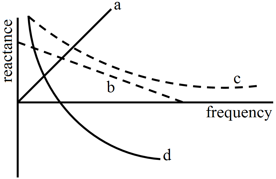
Answer
- (d)
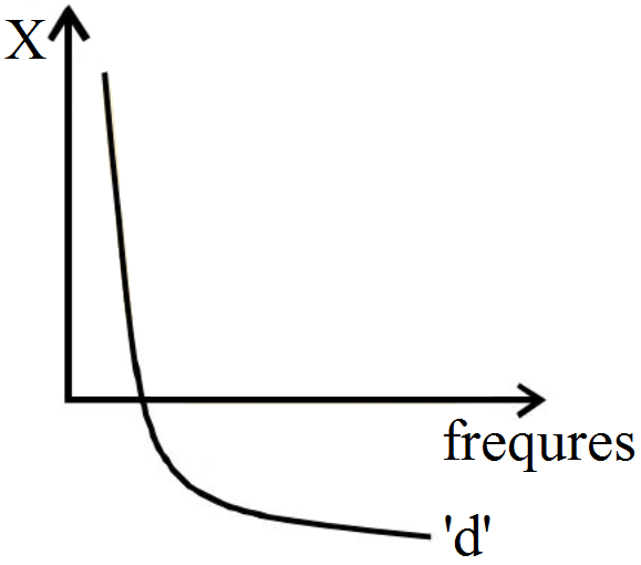
Explanation:
$\text{X}=\text{X}_\text{L}-\text{X}_\text{C}$
$=\omega\text{L}-\frac{1}{\omega\text{C}}$
$=2\pi\text{fL}-\frac{1}{2\pi\text{fC}}$ View full question & answer→Question 1261 Mark
A light bulb is rated at 100W for a 220V supply. Find the peak voltage of the source:
Answer
- 311V
Explanation:
The rated voltage in bulb is rms voltage.
$\text{V}_\text{rms}=\frac{\text{V}_0}{\sqrt{2}}$
$\text{V}_0=\sqrt{2}\times220=311.08\text{V}$ View full question & answer→Question 1271 Mark
In a series LCR circuit the voltage across resistance, capacitance and inductance is 10V each. If the capacitance is short circuited, the voltage across the inductance will be.
Answer
- $\big(\frac{10}{\sqrt{2\text{V}}}\big)$
View full question & answer→Question 1281 Mark
An inductor, a resistor and a capacitor are joined in series with an AC source. As the frequency of the source is slightly increased from a very low value, the reactance of the.
Question 1291 Mark
An inductance of 0.2 H and a resistance of $100\Omega$ are connected in series to an A.C. 180 V, 50 Hz supply. The apparent current flowing in the circuit will be.
View full question & answer→Question 1301 Mark
An alternating current having peak value 14A is used to heat a metal wire. To produce the same heating effect, a constant current i can be used where i is:
Answer
- About 10A.
Explanation:
$\text{I}_\text{p}=14\text{Amp}$
$\text{I}_\text{rms}=\frac{\text{IP}}{\sqrt{2}}=\frac{14}{\sqrt{2}}$
$=9.9=10\text{Amp}.$ View full question & answer→Question 1311 Mark
The correct curve representing the variation of capacitive reactance $Xc$ with frequency $f$ is.
Answer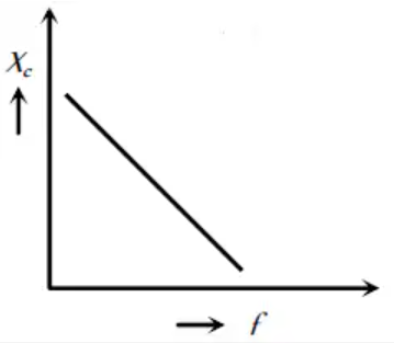
$\text{X}_\text{C}=\frac{1}{\text{C}2\pi\text{f}}$
$X_{C}$ and f are inversely proportional. View full question & answer→Question 1321 Mark
An alternating current is given by $\text{i}=\text{i}_1\cos\omega\text{t}+\text{i}_2\sin\omega\text{t}.$ The rms current is given by:
Answer
- $\sqrt{\frac{\text{i}_1^2+\text{i}_2^2}{2}}$
Explanation:
$\text{i}=\text{i}_1\cos\omega\text{t}+\text{i}_2\sin\omega\text{t}$
$\text{I}_\text{rms}=\frac{\int\limits_0^\text{T}\text{I}^2\text{dt}}{\int\limits_0^\text{T}\text{dt}}$
if $\text{I}=\cos\omega\text{t}$
$\text{I}_\text{rms}^2=\frac{\text{I}_0^2}{2}$
$\text{i}=\text{i}_1\cos\omega\text{t}+\text{i}_2\sin\omega\text{t}$
Than $\text{i}_\text{rms}^2=\frac{\text{i}_1^2}{2}+\frac{\text{i}_2^2}{2}$
$\text{i}_\text{rms}=\sqrt{\frac{\text{i}_1^2+\text{i}_2^2}{2}}$ View full question & answer→Question 1331 Mark
In a circuit, the current lags behind the voltage by a phase difference of $\frac{\pi}{2}$ the circuit will contain which of the following:
Answer
- Only L
Explanation:
In an inductor, current lags behind the input voltage by a phase difference of $\frac{\pi}{2}$.
Current and voltage are in same phase in resistor whereas current leads the voltage by $\frac{\pi}{2}$in a capacitor.
So, the circuit must contain an inductor only. View full question & answer→Question 1341 Mark
Choose the wrong statement of the following:
Answer
- In a pure inductive circuit emf will be in phase with the current
Explanation:
In pure inductive circuit,
voltage leads by $\frac{\pi}{2}$ View full question & answer→Question 1351 Mark
A coil of negligible resistance is connected in series with a $90\Omega$ resistor across a 120 V, 60 Hz line. An ac voltmeter reads 90 V across the resistance, then the inductance of the coil is approximately.
View full question & answer→Question 1361 Mark
Capacitance (C) of the capacitor is.
Question 1371 Mark
The output of a step-down transformer is measured to be $24V$ when connected to a $12$ watt light bulb. The value of the peak current is:
AnswerKey concept: It decreases voltage and increases current
$V_S < V_P$
$N_S > N_P$
$E_S < E_P$
$i_S > i_P$
$R_S < R_P$
$t_S > t_P$
$k < l$
According to the problem output/secondary voltage $V_S = 24V$
Power associated with secondary $P_S = 12W$
$\text{I}_\text{S}=\frac{\text{P}_\text{S}}{\text{V}_\text{S}}=\frac{12}{24}=0.5\text{A}$
Amplitude of the current in the secondary winding
$\text{I}_0=\text{I}_\text{S}\sqrt{2}$
$=(0.5)(1.414)=0.707=\frac{1}{\sqrt{2}}\text{A}$
View full question & answer→Question 1381 Mark
In an $\text{L - C - R}$ circuit the value of $X_L, X_C$ and $R$ are $300\Omega,200\Omega$, and $100\Omega$ respectively. The total impedance of the circuit will be.
AnswerTotal impedance $= R + j(X_L - X_C)$
$=100+\text{j}100$
$=100\sqrt{2}\measuredangle45$
$=141\measuredangle45$
View full question & answer→Question 1391 Mark
In LCR series AC circuit.
Answer
- If R is increased current will decrease.
Explanation:
$\text{I}=\frac{\text{V}}{\text{Z}}=\frac{\text{V}}{\sqrt{\text{R}^2\Big(\omega\text{L }\sim}\frac{1}{\omega\text{C}}\Big)^2}$
By increasing R, current will definitely decrease by change in L or C, current may increase or decrease. View full question & answer→Question 1401 Mark
An alternating voltage$\text{V}=200\sqrt{2}\sin100\text{t},$ Where V is in volt and t is in seconds, is connected to a series combination of $1\mu\text{F}$ capacitor and $10\text{k}\Omega$ resistor through an AC ammeter. The reading of the ammeter will be_____.
Answer
- $10\sqrt{\text{2}}\text{mA}$
Explanation:
$\text{i}=\frac{\text{V}_\text{rms}}{\sqrt{\text{R}^2+\Big(\frac{1}{\omega\text{C}}-\omega\text{L}\Big)^2}}$
$\Rightarrow\text{i}=\frac{200\sqrt{2}\frac{1}{\sqrt{2}}}{\sqrt{10000^2+\Big(\frac{1}{100\times10^{-6}}-100\times0\Big)^2}}=\frac{200}{\sqrt{2\times10000^2}}$
$10\sqrt{\text{2}}\text{mA}$ View full question & answer→Question 1411 Mark
The reactance of a circuit is zero. It is possible that the circuit contains.
Answer
- neither an inductor nor a capacitor
Explanation:
Answer: A an inductor and a capacitor, B neither an inductor nor a capacitor
Reactance in electrical and electronic systems is the opposition of a circuit element to a change of electric current or voltage.Ideally a resistor has zero reactance.
Therefore in a circuit, reactance can be zero either if there are no inductors and capacitors in the circuit, or the individual reactance of inductors and capacitors cancel each other, making net reactance zero.
View full question & answer→Question 1421 Mark
The capacitor offers zero resistance to.
Answer
- A.C. only
Explanation:
Capacitive reactance is given as $\text{X}_\text{C}=\frac{1}{\omega\text{C}}$
From this relation we can see that the value of capacitive reactance and therefore its overall impedance (in Ohms) decreases to zero as the frequency increases acting like a short
circuit. Likewise, as the frequency approaches zero or DC, the capacitors reactance increases to infinity, acting like an open circuit which is why capacitors block DC. View full question & answer→Question 1431 Mark
An alternating voltage $\text{E}=50\sqrt{2}\sin(100\text{t})$ V is connected to a $1\mu\text{F}$ capacitor through an ac ammeter. What will be the reading of the ammeter?
Answer
- $5\text{mA}$
Explanation:
$\text{X}_\text{C}=\frac{1}{\text{C}\omega}=10000\Omega$
ammeater reading $=\text{I}_\text{rms}=\frac{\text{V}_\text{rms}}{\mid\text{jX}_\text{c}\mid}=\frac{50}{10000}=5\text{mA}$ View full question & answer→Question 1441 Mark
The capacitive reactance in an AC circuit is.
Answer
- effective resistance due to capacity
Explanation:
Capacitive reactance in an A.C circuit is: $\text{X}_\text{C}=\frac{1}{\omega\text{C}}\text{ohm}$
where, C is the capacitance of capacitor and $\omega=2\pi\text{rn}$ (n is the frequency of A.C source) View full question & answer→Question 1451 Mark
To convert mechanical energy into electrical energy, one can use:
Answer
- DC dynamo.
- AC dynamo.
Explanation:
DC dynamo or AC dynamo use to convert mechnical energy into electrial energy.
View full question & answer→Question 1461 Mark
In an LCR series a.c. circuit, the voltage across each of the components. L, C and R is 50V. The voltage across the LC combination will be:
Answer
- 0V (zero)
Explanation:
In a series LCR circuit, the voltage across the inductor (L) and the capacitor (C) are in opposite phase.
So the voltage across LC combination will be (50 - 50) = 0V
View full question & answer→Question 1471 Mark
In a RLC circuit capacitance is changed from C to 2C. For the resonant frequency to remain unchanged, the inductance should be changed from L to.
Answer
- $\frac{\text{L}}{2}$
Explanation:
$\text{f}=\frac{1}{2\pi\sqrt{(\text{LC})}}$
when C is doubled, L should be halved so that resonant frequency remains unchanged. View full question & answer→Question 1481 Mark
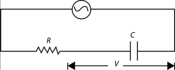
A 50 Hz, 20 V AC source is connected across R series circuit as shown in Figure If the voltage across R is 12V then voltage across capacitor is.
Answer
- 16 V
Explanation:
$\text{V}^2={\text{V}^2_\text{R}}+{\text{V}^2_\text{c}}$
$20^2=12^2+\text{V}^2_\text{c}$
$\text{V}_\text{c}=\sqrt{20^2-12^2}$
$\text{V}_\text{c}=16\text{ V}$ View full question & answer→Question 1491 Mark
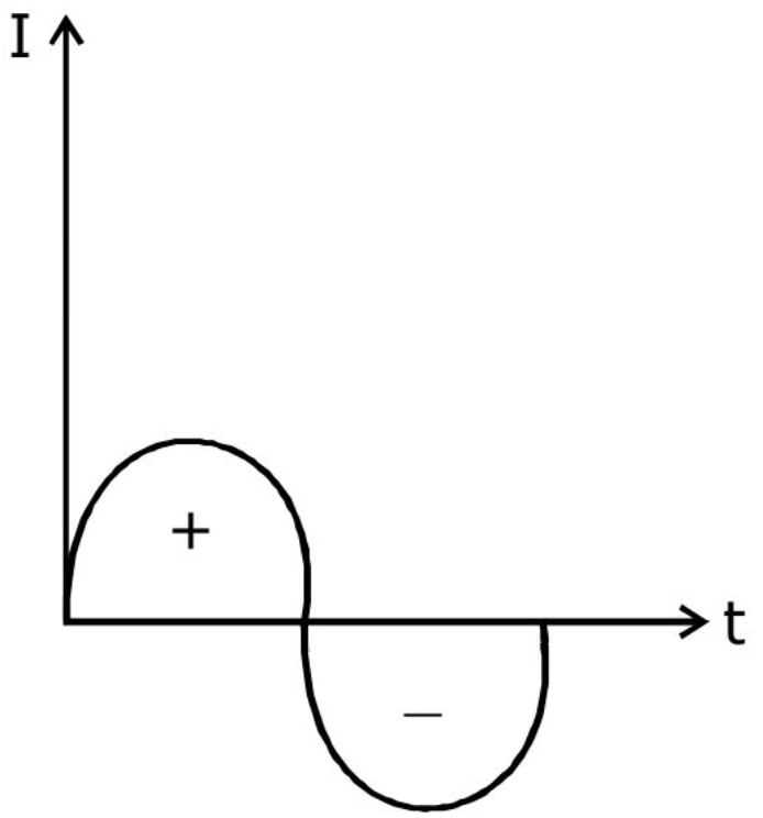
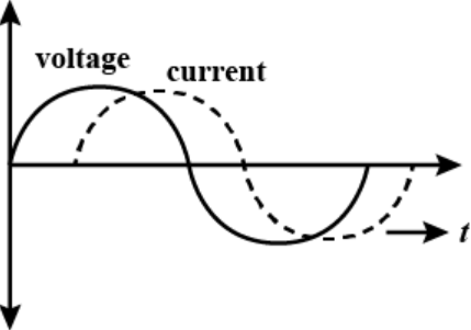
The diagram given show the variation of voltage and current in an AC circuit. The circuit contains.
Answer
- Only a pure inductor
Explantion:
The given circuit shows that the current lags the applied voltage. This is possible if the circuit has inductive element. So, the circuit contain a pure inductor.
View full question & answer→Question 1501 Mark
For the circuit shown in the Figure, the current through the inductor is 0.9 A while the current through the condenser is 0.4 A.
Answer
- I = 0.5 A
Explantion:
The current in inductor and capacitor is always at an phase difference of 180°
for V $=\text{V}_\text{o}\sin\omega\text{t}$
Capacitor, $\text{i}=\text{i}_\text{o}\sin(\omega\text{t}-\frac{\pi}{2})$
Capacitor, $\text{i}=\text{i}_\text{o}\sin(\omega\text{t}+\frac{\pi}{2})$
So, the current from both branches will be 0.9 + (-0.4) = 0.5A View full question & answer→Question 1511 Mark
The reading of voltmeter and ammeter in the following figure will respectively be:
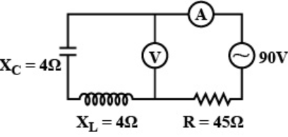
AnswerIn the problem $\text{XC}=4\Omega$ and $\text{XL}=4\Omega$
So, $V$ across $XC$ and $XL$ will be same and in opposite direction, So net voltage will be zero.
Since voltmeter is connected parallel to Capacitor and inductor so, it will read $0$ volts.
Current $=\frac{\text{V}}{\text{impedance}}$
$Z = R$ as $X_L = X_{C}$
Current $=\frac{90}{45}=2\text{A}$
View full question & answer→Question 1521 Mark
The Current in resistance $R$ at resonance is.
AnswerAt resonance $X_L = X_C$
$\Rightarrow R$ current is maximum but finite, which is
$\text{I}_\text{max}=\frac{\text{E}}{\text{R}}$ where $E$ is applied voltag.
View full question & answer→Question 1531 Mark
The power loss in an AC circuit can be minimized by.
Answer
- Decreasing resistance and increasing inductance
Explanation:
In an AC circuit, power loss can be minimized by decreasing in resistance and by increasing in inductance.
View full question & answer→Question 1541 Mark
An inductor $\frac{10\Omega}{60^\circ}$ is connected to a $5\Omega$ resistance in series. Find net impedance.
View full question & answer→Question 1551 Mark
In the given figure as shown, the reading of the ammeter in ampere is.
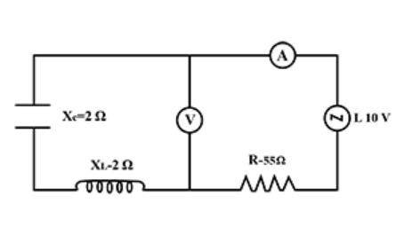
Answer
- 2
Explanation:
$\text{I}=\frac{\text{E}}{\sqrt{\text{R}^2+(\text{X}_\text{L}-\text{X}_\text{C})^2}}$
$=\frac{110}{\sqrt{55^2+(2-2)^2}}$
$=\frac{110}{55}=2\text{A}$ View full question & answer→Question 1561 Mark
In the circuit shown in fig., the resonant frequency is.
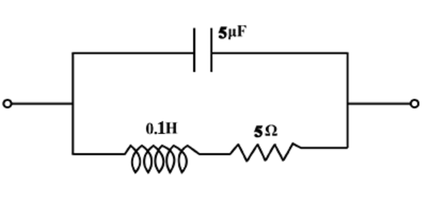
Answer
- 225.08Hz
Explanation:
The resonant frequecy of a circuit is given by $\text{f}=\frac{1}{2\pi\sqrt{\text{LC}}}$
Given $\text{L}=0.1\text{H }\text{C}=5\mu\text{F }\text{R}=5\Omega$
Substituting them in formula for f gives
f = 225.08 Hz. View full question & answer→Question 1571 Mark
In the figure two identical bulbs, each with filament resistance $100\Omega$ are connected to a resistor $\text{R}=100\Omega$ and an inductor $(\text{X}_\text{L}=100\Omega)$ as shown in the Figure. Then, which bulb glows more.
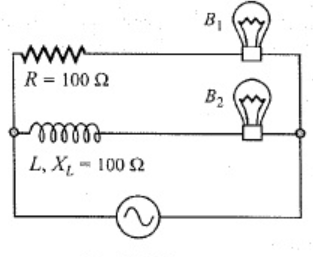
AnswerImpedance in branch containing bulb$1$
$\text{Z}_1=200\Omega$
impedance in branch containing bulb$2$
$\text{Z}_2\sqrt{\text{R}^2+\text{X}_\text{L}}^2$
$\text{Z}_2=\sqrt{100^2+100^2}$
$\text{Z}_2=100\sqrt{2}$
Since,
$\text{Z}_1>\text{Z}_2$
$B_2$ will glow more than $B_1.$
View full question & answer→Question 1581 Mark
In a circuit inductance $L$ and capacitance $C$ are connected as shown in figure. $A_{1}$ and $A_2$ are ammeters.
When key $K$ is pressed to complete the circuit, then just after closing key $(K),$ the readings of $A_{1 }$ and $A_2$ will be.
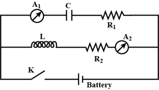
AnswerInitially there is no $D.C$ current in inductive circuit and maximum $D.C$ current is in capacitive current.
Hence, the current is zero in $A_{2}$ and maximum in $A_{1}$
View full question & answer→Question 1591 Mark
In above circuit, what is the potential drop across $ZY?$
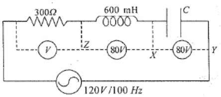
Answer$V_{ZY} = VC - VL = 0$
View full question & answer→Question 1601 Mark
In the $AC$ network shown in figure, the rms current flowing through the inductor and capacitor are $0.6A$ and $0.8A$ respectively. Then the current coming out of the source is
Answer$I_C$ is $90^\circ$ ahead of the applied voltage and $I_{L}$ lags behind the applied voltage by $90^\circ .$
So, there is a phase difference of $180^\circ$ between $IL$ and $IC$
$\therefore I = I_C - I_L = 0.2A$
View full question & answer→Question 1611 Mark
In the given circuit $R$ in pure resistance and $X$ is unknown circuit element. An $AC$ voltage source is applied across $A$ and $C$. If $V_{AB} = V_{AC},$ then $X$ is.
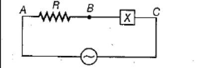
AnswerSince the voltage across the resistive element is same as the voltage applied, the voltage drop across $BC$ is zero. This is possible only when the ohmic value of the element connected across $BC$ is zero.
So$, X$ should be combination of inductance and capacitance at resonance.
View full question & answer→Question 1621 Mark
In the following circuit the values of $L, C, R$ and $E_0$ are $0.01 H, 10^{-5}F, 25\Omega$ and $220$volt respectively. The value of current flowing in the circuit at $f = 0$ and $\text{f}=\infty$ will respectively be.
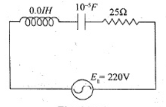
Answer$\text{I}=\frac{220}{25+\text{j}\Big(0.1\times2\pi\text{f }-\frac{1}{10^{-5}2\pi\text{f}}\Big)}$
$\text{I}=0\text{ at }\text{f}=0$
$\text{I}=0\text{ at }\text{f}=\infty$
View full question & answer→Question 1631 Mark
In the following diagram, the value of emf of A.C. source will be:
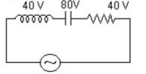
Answer
- $40\sqrt{2}\text{V}$
Explanation:
$\text{E}_\text{rms}=\sqrt{\text{V}^2_\text{R}+(\text{V}_\text{L}-\text{V}_\text{c})^2}$
$=\sqrt{40^2+(40-80)^2}$
$=\sqrt{40^2+40^2}$
$=40\sqrt{2}\text{V}$ View full question & answer→Question 1641 Mark
In an $\text{LCR}$ circuit as shown below both switches are open initially. Now switch $S_1$ is closed, $S_2$ kept open. $(q$ is charge on the capacitor and $\tau=\text{RC}$ is capacitive time constant$).$ Which of the following statement is correct?
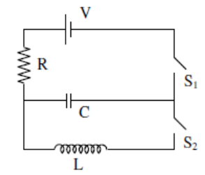
AnswerCharge on the capacitor at any time $`t\ '$ is
$\text{q}=\text{CV}(1-\text{e}\frac{-\text{t}}{\tau})$
at $\text{t}=2\tau$
$\text{q}=\text{CV}(1-\text{e}^{-2})$
View full question & answer→Question 1651 Mark
The adjoining figure shows an $AC$ circuit with resistance $R,$ inductance $L$ and source voltage $Vs$. Then.
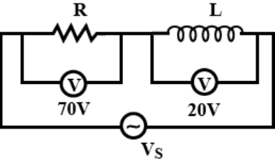
AnswerThe source voltage $V_{s} = 72.8V.$
View full question & answer→Question 1661 Mark
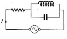
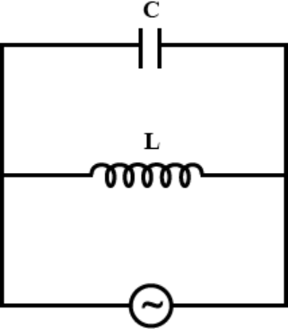
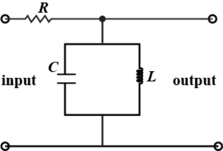
The circuit shown in Fig. acts as a.
Answer
- tuned filter
Explanation:
The circuit shown in figure has capacitor and inductor in parallel so their will be current flowing continuously with energy being transformed into electrical in capacitor and magnetic in inductor, hence it is a tuned filter.
View full question & answer→Question 1671 Mark
A $6\ kHz$ sinusoidal voltage is applied to a series $RC$ circuit. The frequency of the voltage across the resistor is.
AnswerFrequency of applied voltage and voltage or current accross any component are same.
As we know,
$\text{I}=\frac{\text{V}}{\text{Z}}$ and $Z$ has nothing to do with frequency
$\Rightarrow\ I$ and $V$ have same frequency.
And also according to $\text{KVL V} = V_1 + V_2 + V_{3}$
$\Rightarrow$ voltage and current across any component have same frequency i.e $6\ kHz$.
View full question & answer→Question 1681 Mark
In the circuit shown in the figure, (neglecting source resistance) the voltmeter and ammeter readings will respectively be.
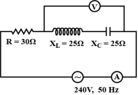
Answer
- 0 V, 8 A
Explanation:
Voltmeter reading is zero since voltage in both Capacitor and inductor is same in magnitude but opposite in sign because current in series is same and both have same reactance.
So, $\text{i}=\frac{\text{V}}{\text{R}}$
$=\frac{240}{30}$
$=8\text{A}$ View full question & answer→Question 1691 Mark
In the given circuit what is the potential drop across resistance?
Answer
- 120 V
Explanation:
At resonance the voltage across L and C are same but opposite.
So, at resonance $\mid\text{V}_\text{L}\mid=\mid\text{V}_\text{C}\mid$
$\therefore\text{V}_\text{R}=\text{V}_\text{app}=120\text{V}$ View full question & answer→Question 1701 Mark
The natural frequency of an LC - circuit is 1,25,000 cycles per second. Then the capacitor C is replaced by another capacitor with a dielectric medium of dielectric constant k. In this case, the frequency decreases by 25kHz. The value of k is:
Question 1711 Mark
A resistance R and a capacitor C are joined to a source of AC of constant e.m.f and variable frequency. The potential difference across C is V. If the frequency of AC is gradually increased, V will
Answer
- decrease
Explanation:
In complex plane $\text{V}=\frac{\text{V}_\text{AC}}{1+\text{jRC}\omega}$
Therefore as $\omega$(frequency) increases, V decreases. View full question & answer→Question 1721 Mark
An alternating current generator has an internal resistance $R_g$ and an internal reactance $X_g.$ It is used to supply power to a passive load consisting of a resistance $R_g$ and a reactance $X_L.$ For maximum power to be delivered from the generator to the load, the value of $X_L$ is equal to:
AnswerFor maximum power to be delivered from the generator $($or internal reactance $X_g)$ to the load $($of reactance$, X_L),$
$\Rightarrow X_L + X_g = 0\ ($the total reactance must vanish$)$
$\Rightarrow X_L= -X_g.$
View full question & answer→Question 1731 Mark
If the output is taken across a capacitor in a series RLC circuit then it acts as.
Answer
- low-pass filter
Explanation:
Given circuit is one simple low-pass filter circuit consists of a resistor in series with a load, and a capacitor in parallel with the load. The capacitor exhibits reactance, and blocks low-frequency signals, forcing them through the load instead. At higher frequencies the reactance drops, and the capacitor effectively functions as a short circuit.
View full question & answer→Question 1741 Mark
In the following circuit, the values of current flowing in the circuit at f = 0 and $\text{f}=\infty$ will respectively be.
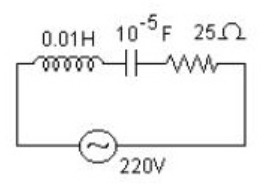
Answer
- 0A and 0A
Explanation:
In a LCR circuit current at t = 0 is zero because inductor does not allow flow of current,
and at t = ∞ also current is zero because capacitor does not allow flow of current.
View full question & answer→Question 1751 Mark
The frequency of oscillation of current in the inductor is.
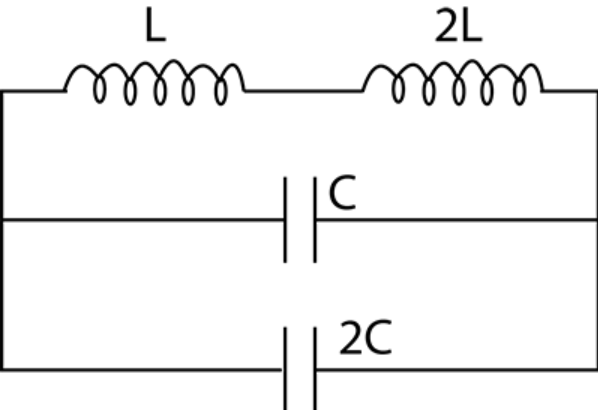
Answer
- $\frac{1}{6\pi\sqrt{\text{LC}}}$
Explanation:
Equivalent inductance Leq = L + 2L = 3L
Ceq = C + 2C = 3C
$\therefore$ Frequency of oscillation $\text{f}=\frac{1}{2\pi\sqrt{\text{L}_\text{eq}\text{C}_\text{eq}}}=\frac{1}{6\pi\sqrt{\text{LC}}}$ View full question & answer→Question 1761 Mark
A coil has an inductance of 0.7 H and is joined in series with a resistance of $220\Omega$ When an alternating emf of 220V at 50 cps is applied to it, then the wattless component of the current in the circuit is $(\text{take }0.7\pi=2.2)$
Answer
- 0.5 A
Explanation:
Wattless current $=\text{I}_\text{max}\sin(\tan^{-1}[\frac{\text{L}\omega}{\text{R}}])=\frac{220}{\sqrt{\text{R}^2+\text{L}^2\omega^2}}\sin(\tan^{-1}[\frac{\text{L}\omega}{\text{R}})=0.5\text{A}$ View full question & answer→MCQ 1771 Mark
In a transformer 220 ac voltage is increased to 2200 volts. If the number of turns in the secondary are 2000, then the number of turns in the primary will be