MCQ 11 Mark
The line that draws power supply to your house from street has:
AnswerSolution:
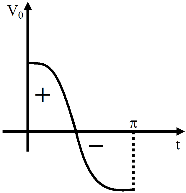
Alternation currents are used for household supplies, which are having zero average value over a cycle.
The line is having some resistance, so power factor $\cos\phi=\frac{\text{R}}{\text{Z}}\neq0$
So, $\phi\neq\frac{\pi}{2}\Rightarrow\ \phi<\frac{2}{\pi}$
i.e., phase lies between 0 and $\frac{\pi}{2}$.
Important point: The average value of alternating quantity for one complete cycle is zero.
The average value of ac over half cycle $\Big(\text{t}=0\text{ to }\frac{\text{T}}{2}\Big)$
$\text{i}_\text{av}=\frac{\int_0^{\frac{\text{T}}{2}}\text{idt}}{\int_0^{\frac{\text{T}}{2}}\text{dt}}=0.637\text{i}_0=63.7\% \ \text{of i}_0$
Similarly $\text{V}_\text{av}=\frac{2\text{V}_0}{\pi}=0.637\text{V}_0=63.7\%\ \text{of V}_0.$
View full question & answer→MCQ 21 Mark
When a voltage measuring device is connected to $AC$ mains, the meter shows the steady input voltage of $220V$. This means,
- A
Input voltage cannot be $AC$ voltage, but a $DC$ voltage.
- B
Maximum input voltage is $220V.$
- ✓
The meter reads not v but $\left\langle v^2\right\rangle a$ and is calibrated to read $\sqrt{<\text{v}^2>}$.
- D
The pointer of the meter is stuck by some mechanical defect.
AnswerCorrect option: C. The meter reads not v but $\left\langle v^2\right\rangle a$ and is calibrated to read $\sqrt{<\text{v}^2>}$.
View full question & answer→MCQ 31 Mark
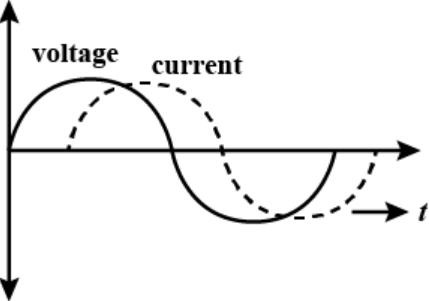
The diagram given show the variation of voltage and current in an $AC$ circuit. The circuit contains.
- A
- ✓
- C
- D
A capacitor and and inductor
AnswerThe given circuit shows that the current lags the applied voltage. This is possible if the circuit has inductive element. So, the circuit contain a pure inductor.
View full question & answer→MCQ 41 Mark
The $AC$ produced in India changes its direction in every:
AnswerCorrect option: A. $\frac{1}{100}\text{second}$
In India, the frequency of $AC$ voltage is $50 Hz.$
It means $50$ waves will be produced in $1 s.$
In one wave, the direction is changed $2$ times.
Thus, in $50$ waves, the direction will be altered $50 \times 2 = 100$ times.
i.e. the direction is changed $100$ times in $1 s.$
Thus the direction is changed in every $\frac{1}{100}\text{second}$
View full question & answer→MCQ 51 Mark
To reduce the reasonant frequency in an $\text{LCR}$ series circuit with a generator:
- A
The generator frequency should be reduced.
- ✓
Another capacitor should be added in parallel to the first.
- C
The iron core of the inductor should be removed.
- D
Dielectric in the capacitor should be removed.
AnswerCorrect option: B. Another capacitor should be added in parallel to the first.
Key Concept: Resonant frequency $($Natural frequency$)$
At resonance $\text{X}_\text{L}=\text{X}_\text{C}\Rightarrow\ \omega_0\text{L}=\frac{1}{\omega_0\text{C}}$
$\Rightarrow\ \omega_0=\frac{1}{\sqrt{\text{LC}}}\frac{\text{red}}{\sec}$
$\Rightarrow\ \text{v}_0=\frac{1}{2\pi\sqrt{\text{LC}}}\text{Hz}$
Resonant frequency in an $L-C-R$ circuit is given by
$\text{v}_0=\frac{1}{2\pi\sqrt{\text{LC}}}$
If $L$ or $C$ increases, the resonant frequency will reduce.
To increase capacitance, we must connect another capacitor parallel to the first.
View full question & answer→MCQ 61 Mark
An $AC$ voltmeter in an $L - C - R$ circuit reads $30$ volt across resistance, $80$ volt across inductance and $40$ volt across capacitance. The value of applied voltage will be.
- ✓
$50$ Volt
- B
$25$ Volt
- C
$150$ Volt
- D
$70$ Volt
AnswerCorrect option: A. $50$ Volt
$\text{V}=\sqrt{\text{V}^2_\text{R}+(\text{V}_\text{L}-\text{V}_\text{C})^2}$
$\text{V}=\sqrt{30^2+(80-40)^2}$
$\text{V}=50\text{ Volt}$
View full question & answer→MCQ 71 Mark
In series combination of $\text{R, L, C}$ with an $A.C$ source at resonanace, if $R = 20$ ohm, then impedence $Z$ of the combination is.
- ✓
$20$ ohm
- B
- C
$10$ ohm
- D
$400$ ohm
AnswerCorrect option: A. $20$ ohm
We know at resonance, reactance $($resistance due to inductor and capacitor$)$ be zero $(0).$
At resonance, Impedance $(Z) =$ Resistance $(R)$
Therefore, $Z = 20$ ohm
View full question & answer→MCQ 81 Mark
In an $\text{LCR}$ circuit the capacitance is made $\frac{1^\text{th}}{4}$ then what should be the change in inductance that the circuit remains in resonance again?
AnswerCorrect option: D. $4$ times
$\text{f}_0=\frac{1}{2\pi\sqrt{\text{LC}}}.$
View full question & answer→MCQ 91 Mark
In an $\text{LCR}$ circuit the potential difference between the terminal of the inductance is $60V$, between the terminals of the capacitor is $30V$ and that between the terminals of the resistance is $40V$. The supply voltage will be equal to:
- A
$130V$
- B
$10V$
- ✓
$50V$
- D
$70V$
AnswerSupply voltage of an $\text{LCR}$ circuit
$\text{V}=\sqrt{\text{V}^2_\text{R}+(\text{V}_\text{L}-\text{V}_\text{C})^2}$
since inductor and capacitor potentials are out of phase with each other
$=\sqrt{40^2+(60-30)^2\text{V}}$
$=50\text{V}$
View full question & answer→MCQ 101 Mark
The values of $X_L, X_C$ and $R$ in series with an $A.C.$ circuit are $8 \Omega, 6 \Omega$ and $10 \Omega$ respectively. The total impedance of the circuit will be $\qquad$ $\Omega$
- ✓
$10.2$
- B
$12.2$
- C
$10$
- D
$24.4$
AnswerCorrect option: A. $10.2$
$\text{Z}=\sqrt{\text{R}^2+(\text{X}_\text{L}-\text{X}_\text{C})^2}$
$=\sqrt{(10)^2+(8-6)^2}$
$=\sqrt{10^2+2^2}$
$=\sqrt{100+4}$
$=10.2\Omega$
View full question & answer→MCQ 111 Mark
The resultant reactance in an $L - C - R$ circuit is.
AnswerCorrect option: B. $X _{ L }- x _{ C }$
Reactance is the nonresistive component of impedance in an $AC$ circuit, arising from the effect of inductance or capacitance or both and causing the current to be out of phase with the electromotive force causing it.
Therefore, reactance of the $L - C - R$ circuit is $X _{ L }- x _{ C }$
View full question & answer→MCQ 121 Mark
An inductor of reactance $1 \Omega$ and a resistor of $2 \Omega$ are connected in series to the terminals of a $6 V (rms) a.c.$ source. The power dissipated in the circuit is:
- A
$8W.$
- B
$12W.$
- ✓
$14.4W.$
- D
$18W.$
AnswerCorrect option: C. $14.4W.$
According to the problem, $X _{ L }=1 \Omega, R =2 \Omega$,
$E _{ rms }=6 V, P _{ av }=?$
Average power dissipated in the circuit
$\text{P}_\text{av}=\text{E}_\text{rms}\text{I}_\text{rms}\cos\phi \ .....(\text{i})$
$\text{I}_\text{rms}=\frac{\text{E}_\text{rms}}{\text{Z}}$
$\text{Z}=\sqrt{\text{R}^2+\text{X}^2_\text{L}}$
$=\sqrt{4+1}=\sqrt{5}$
$\text{I}_\text{rms}=\frac{6}{\sqrt{5}}\text{A}$
$\cos\phi=\frac{\text{R}}{\text{Z}}=\frac{2}{\sqrt{5}}$
$\text{P}_\text{av}=6\times\frac{6}{\sqrt{5}}\times\frac{2}{\sqrt{5}}\ \ [\text{from Eq. (i)]}$
$=\frac{72}{\sqrt{5}\sqrt{5}}=\frac{72}{5}=14.4\text{W}$
View full question & answer→MCQ 131 Mark
Current in the circuit is wattless, if.
- A
Inductance in the circuit is zero
- ✓
Resistance in the circuit is zero
- C
- D
Resistance and inductance both are zero
AnswerCorrect option: B. Resistance in the circuit is zero
Current in the circuit is wattless,
Because power $=i^2 R$, if $R=0$, then $P=0$.
View full question & answer→MCQ 141 Mark
If a capacitor is connected to two different $A.C.$ generators, then the value of capacitive reactance is:
- A
directly proportional to frequency
- ✓
inversely proportional to frequency
- C
- D
inversely proportional to the square of frequency
AnswerCorrect option: B. inversely proportional to frequency
$\text{X}_\text{C}=\frac{1}{\omega\text{c}}$
$\therefore\text{X}_\text{C}\propto\frac{1}{\omega}$
View full question & answer→MCQ 151 Mark
An inductive coil has resistance of $100 \Omega$ When an ac signal of frequency $1000 \ Hz$ is fed to the coil, the applied voltage leads the current by $45^{\circ}$. What is the inductance of the coil?
- A
$2mH$
- B
$3.3mH$
- ✓
$16mH$
- D
$\sqrt{5}\text{mH}$
AnswerCorrect option: C. $16mH$
$\tan(45)=1\frac{\text{L}\omega}{\text{R}}$
$\text{L}=\frac{\text{R}}{\omega}=\frac{\text{R}}{(2\pi1000)}=.016\text{H}$
View full question & answer→MCQ 161 Mark
When the frequency of $\text{AC}$ is doubled, the impedance of an $\text{LCR}$ series circuit:
View full question & answer→MCQ 171 Mark
Statement $A:$ With an increase in the frequency of $AC$ supply inductive reactance increases.
Statement $B:$ With an increase in the frequency of $AC$ supply capacitive reactance increase.
- ✓
$A$ is true but $B$ is false
- B
Both $A$ and $B$ are true
- C
$A$ is false but $B$ is true
- D
Both $A$ and $B$ are false
AnswerCorrect option: A. $A$ is true but $B$ is false
$\text{Z}_\text{L}=\text{WL}\ \ \ \text{Z}_\text{C}=\frac{1}{\text{WC}}$
$\text{w}\uparrow,\text{Z}_\text{L}\uparrow\text{Z}_\text{c}\downarrow$
View full question & answer→MCQ 181 Mark
If the phase difference between Alternating Voltage and Alternating Current is $\frac{\pi}{6}$ and the resistance in the circuit is $\sqrt{300}\Omega,$ then the impedance of the circuit will be.
- A
$25\Omega$
- B
$50\Omega$
- ✓
$20\Omega$
- D
$100\Omega$
AnswerCorrect option: C. $20\Omega$
$\text{impedance}×\cos\theta = \text{resistance}$
$\text{impedance} = \frac{\text{resistance}}{\cos\theta}$
$=\frac{\sqrt{300}}{\frac{\cos\pi}{6}}$
$20\Omega$
View full question & answer→MCQ 191 Mark
If the value of $C$ in a series $\text{RLC}$ circuit is decreased, the resonant frequency.
AnswerResonant frequency in the series $\text{RLC}$ circuit $\text{v}_\text{r}=\frac{1}{2\pi\sqrt{\text{LC}}}$
$\Rightarrow\text{v}_\text{r}\propto\frac{1}{\sqrt{\text{C}}}$
Thus resonant frequency of the circuit increases if the value of $C$ decreases.
View full question & answer→MCQ 201 Mark
The phase angle between current and voltage in a purely inductive circuit is:
- A
$\text{zero}$
- B
$\pi$
- C
$\frac{\pi}{4}$
- ✓
$\frac{\pi}{2}$
AnswerCorrect option: D. $\frac{\pi}{2}$
In the above image waveform of current and voltage in puerly inductive circuit with time is shown.
It is clear from the image that current lags voltage by $90^\circ .$
Hence phase angle between current and voltage in purely inductive circuit is $\frac{\pi}{2}$
View full question & answer→MCQ 211 Mark
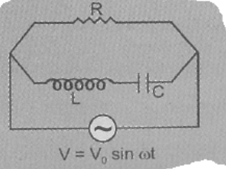
For the circuit shown in the Figure, the current through the inductor is $0.9$ A while the current through the condenser is $0.4 A.$

AnswerCorrect option: C. $I = 0.5 A$
The current in inductor and capacitor is always at an phase difference of $180^\circ $
for $V =\text{V}_\text{o}\sin\omega\text{t}$
Capacitor, $\text{i}=\text{i}_\text{o}\sin(\omega\text{t}-\frac{\pi}{2})$
Capacitor, $\text{i}=\text{i}_\text{o}\sin(\omega\text{t}+\frac{\pi}{2})$
So, the current from both branches will be $0.9 + (-0.4) = 0.5A$
View full question & answer→MCQ 221 Mark
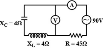
The reading of voltmeter and ammeter in the following figure will respectively be:
- ✓
$0$ and $2A$
- B
$2A$ and $0V$
- C
$2V$ and $2A$
- D
$0V$ and $0A$
AnswerCorrect option: A. $0$ and $2A$
In the problem $\text{XC}=4\Omega$ and $\text{XL}=4\Omega$
So, $V$ across $XC$ and $XL$ will be same and in opposite direction, So net voltage will be zero. Since voltmeter is connected parallel to Capacitor and inductor so, it will read $0$ volts.
Current $=\frac{\text{V}}{\text{impedance}}$
$Z=R$ as $X_L=X_C$
Current $=\frac{90}{45}=2\text{A}$
View full question & answer→MCQ 231 Mark
The instantaneous voltage through a device of impedence $20\Omega$ is $\text{e}=80\sin100\pi\text{t}.$The effective value of the current is.
- A
$3A$
- ✓
$2.828A$
- C
$1.732A$
- D
$4A$
AnswerCorrect option: B. $2.828A$
Given equation, $e =80 \sin 100 \pi t. (i)$
Standard equation of instantaneous voltage given by $E = e_m \sin (\omega t) \ldots \ldots (i)$
Compare $(i)$ and $(ii)$, we get $e _{ m }=80 V$ where $e _{ m }$ is the voltage amplitude.
Current amplitude $I _{ m }=\frac{ e _{ m }}{ Z }$ where $Z =$ impedence
$=\frac{80}{20}=4 A$
$I _{ r . m . s }=\frac{4}{\sqrt{2}}=\frac{4 \sqrt{2}}{2}=2 \sqrt{2}=2.828 A$
View full question & answer→MCQ 241 Mark
The Current in resistance $R$ at resonance is.
AnswerAt resonance $X_L=X_C$
$\rightarrow R\ \& $ current is maximum but finite, which is
$\text{I}_\text{max}=\frac{\text{E}}{\text{R}}$ where $E$ is applied voltag.
View full question & answer→MCQ 251 Mark
In a circuit $L, C$ and $R$ are connected in series with an alternating voltage source of frequency $f$. The current leads the voltage by $45^{\circ}$. The value of $C$ is.
- A
$\frac{1}{2\pi\text{f}(2\pi\text{fL - R})}$
- ✓
$\frac{1}{2\pi\text{f}(2\pi\text{fL + R})}$
- C
$\frac{1}{\pi\text{f}(2\pi\text{fL - R})}$
- D
$\frac{1}{\pi\text{f}(2\pi\text{fL + R})}$
AnswerCorrect option: B. $\frac{1}{2\pi\text{f}(2\pi\text{fL + R})}$
Here $X_L=X_C = R$
$\Rightarrow\frac{1}{2\pi\text{f}}=(\text{R}+2\pi\text{fL})$
$\Rightarrow\text{C}=\frac{1}{2\pi\text{f}(2\pi\text{fL + R})}$
View full question & answer→MCQ 261 Mark
The capacitive reactance of $50 \mu F$ capacitance at a frequency of $2 \times 10^3 Hz$ will be$........ \Omega$
- A
$\frac{2}{\pi}$
- B
$\frac{3}{\pi}$
- C
$\frac{4}{\pi}$
- ✓
$\frac{5}{\pi}$
AnswerCorrect option: D. $\frac{5}{\pi}$
Capacitive reactance $=\frac{1}{\omega\text{c}}$
$=\frac{1}{2\pi\text{fc}}$
$=\frac{1}{2\pi2\times10^3\times50\times10^{-6}}$
$=\frac{5}{\pi}\Omega$
View full question & answer→MCQ 271 Mark
The impedance of a series $\text{L - C - R}$ circuit in an $AC$ circuit is.
AnswerCorrect option: D. $\text{None of these}$
$\text{Z}=\sqrt{\text{R}^2+(\text{X}_\text{L}-\text{X}_\text{C})^2}$
View full question & answer→MCQ 281 Mark
Alternating current is one which changes in its:
- A
- B
- ✓
magnitude and direction both
- D
AnswerCorrect option: C. magnitude and direction both
An alternating current $(AC)$ is an electric current whose magnitude and direction vary, unlike direct current, whose direction remains constant.
The usual waveform of an $AC$ power circuit is a sine wave, because this leads to the most efficient transmission of energy. The sine wave oscillates periodically between positive and negative direction.
View full question & answer→MCQ 291 Mark
A steady potential difference of $100V$ produces heat at a constant rate in a resistor. The alternating voltage which will produce half the heating effect in the same resister will be.
- ✓
$100V$
- B
$50V$
- C
$70.7V$
- D
$141.4V$
AnswerCorrect option: A. $100V$
The power supplied to the resistor by $DC$ source $=\frac{\text{V}^2_\text{dc}}{\text{R}}$
Energy given by $AC$ source $\int_{0}^{\text{T}}=\frac{\text{V}^2_0}{\text{R}}\text{dt}$
Hence, $\int_{0}^{\text{T}}=\frac{\text{V}^2_0\sin^2\omega\text{t}}{\text{R}}\text{dt}=\frac{1}{2}\times\frac{\text{V}^2_\text{dc}\text{T}}{\text{R}}$
$\Rightarrow\text{V}_0=\text{V}_\text{dc}=100\text{V}$
View full question & answer→MCQ 301 Mark
A $220V$ main supply is connected to a resistance of $100\text{k}\Omega$ The effective current is?
AnswerCorrect option: A. $2.2\text{mA}$
Effective current is the rms value. Here, $220V$ is the labelled value of $AC$ which is also the rms value. Hence,
$\text{I}_\text{rms}=\frac{\text{E}_\text{rms}}{\text{R}}$
$\text{I}_\text{rms}=\frac{220}{100\times10^3}$
$\text{I}_\text{rms}=2.2{\text{mA}}$
View full question & answer→MCQ 311 Mark
In the figure two identical bulbs, each with filament resistance $100\Omega$ are connected to a resistor $\text{R}=100\Omega$ and an inductor $(\text{X}_\text{L}=100\Omega)$ as shown in the Figure. Then, which bulb glows more.
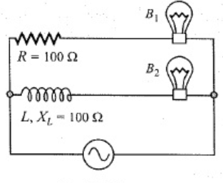
AnswerImpedance in branch containing bulb$1$
$\text{Z}_1=200\Omega$
impedance in branch containing bulb$2$
$\text{Z}_2\sqrt{\text{R}^2+\text{X}_\text{L}}^2$
$\text{Z}_2=\sqrt{100^2+100^2}$
$\text{Z}_2=100\sqrt{2}$
Since,
$\text{Z}_1>\text{Z}_2$
$B_2$ will glow more than $B_1$
View full question & answer→MCQ 321 Mark
An inductance and resistance are connected in series with an $A.C$ circuit. In this circuit.
- A
the current and $P.d.$ across the resistance lead $P.d$ across the inductance by $\frac{\pi}{2}$
- ✓
the current and $P.d$ across the resistance lags behind the $P.d$. across the inductance by angle $\frac{\pi}{2}$
- C
The current across resistance leads and the $P.d$ across resistance lags behind the $P.d$ across the inductance by $\frac{\pi}{2}$
- D
the current across resistance lags behind and the $P.d$ across the resistance leads the $P.d$ across the inductance by $\frac{\pi}{2}$
AnswerCorrect option: B. the current and $P.d$ across the resistance lags behind the $P.d$. across the inductance by angle $\frac{\pi}{2}$
This is very fundamental. If we apply separate voltages across resistance and inductor, then in resistance, current and voltage both are in same phase whereas in inductor, current across it lags p.d across it by $\frac{\pi}{2}.$
Now, when we apply voltage across inductor and resistance connencted in series then current through both of them will be same because of $\text{KCL.}$ therefore voltage across resistor will be in same phase with current whereas voltage across inductor will lead the current across it by $\frac{\pi}{2}.$ therefore current and voltage across resistor lags voltage across inductor by $\frac{\pi}{2}$
View full question & answer→MCQ 331 Mark
A constant current of $2.8A$ exists in a resistor. The rms current is:
- ✓
$2.8A.$
- B
About $2A$.
- C
$1.4A.$
- D
Undefined for a direct current.
AnswerCorrect option: A. $2.8A.$
A constant current exists in a resistor is rms current it is equal to $2.8Amp.$
View full question & answer→MCQ 341 Mark
For watt$-$less power in an $AC$ circuit the phase angle between the current and voltage is.
- A
$0^{\circ}$
- ✓
$90^{\circ}$
- C
$45^{\circ}$
- D
AnswerCorrect option: B. $90^{\circ}$
Watt$-$less power in an $AC$ circuit is basically power supposed to be generated by inductive and capacitive reactance and since they are not resistor they generate any heat, and these power wasted is called watt$-$less power and its phase angle is always $90^{\circ}$ as it has only capacitor and inductor.
View full question & answer→MCQ 351 Mark
An inductor, a resistor and a capacitor are joined in series with an $AC$ source. As the frequency of the source is slightly increased from a very low value, the reactance of the.
View full question & answer→MCQ 361 Mark
The frequency of $A.C$ mains in India is.
- A
$30Hz$
- ✓
$50Hz$
- C
$60Hz$
- D
$120Hz$
AnswerCorrect option: B. $50Hz$
In India, the $AC$ mains supply is referred to as single$-$phase alternating current and corresponds to a voltage of $230 V$ at a frequency of $50Hz$, similar to most European countries. Whereas in the $\text{USA, AC}$ mains supply uses $60Hz.$
View full question & answer→MCQ 371 Mark
The $AC$ voltage across a resistance can be measured using:
AnswerCorrect option: B. A hot$-$wire voltmeter.
The $AC$ voltae across a resustance can be measured using a hot$-$wore volmeter.
View full question & answer→MCQ 381 Mark
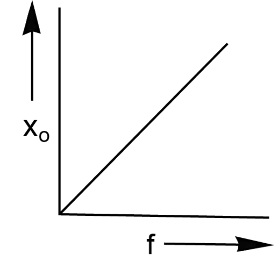
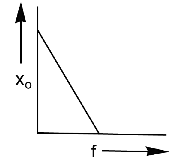
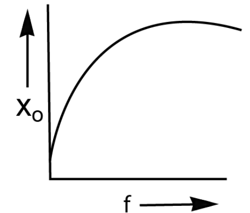
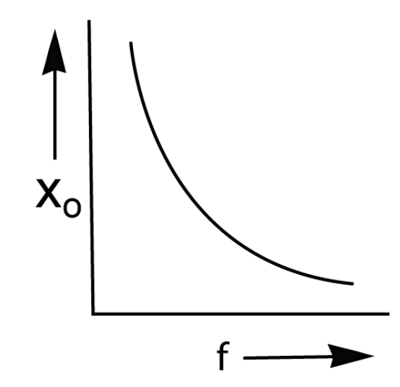
Which one of the following graphs in following figure represents variation of reactance ' $X_c^{\prime}$ of a capacitor with frequency ' $f$ ' of an ac supply?
AnswerCapacitor reactance is given by: $\text{X}_\text{c}=\frac{1}{2\pi\text{fC}}$
C is the capacitance.
$X_c\ \&$ f are inversely proportional.
View full question & answer→MCQ 391 Mark
An inductor has a resistance $R$ and inductance $L$. It is connected to an $AC$ source of emf $Ev$ and angular frequency $ω$; then the current $Iv$ in the circuit is:
- A
$\frac{\text{E}_\text{v}}{\omega\text{L}}$
- B
$\frac{\text{E}_\text{v}}{\text{R}}$
- ✓
$\frac{\text{E}_\text{v}}{\sqrt{\text{R}^2+\omega^2\text{L}^2}}$
- D
$\sqrt{\Big(\frac{\text{E}_\text{v}}{\text{R}}\Big)^2+\Big(\frac{\text{E}_\text{v}}{\omega\text{L}}\Big)^2}$
AnswerCorrect option: C. $\frac{\text{E}_\text{v}}{\sqrt{\text{R}^2+\omega^2\text{L}^2}}$
The impedance in $R-L$ circuit is
$\text{Z}=\sqrt{\text{R}^2+{\text{X}^2_\text{L}}}=\sqrt{\text{R}^2+{(\omega\text{L})^2}}$
The current $\text{I}_\text{V}=\frac{\text{E}_\text{V}}{\text{Z}}$
$\frac{\text{E}_\text{v}}{\sqrt{\text{R}^2+\omega^2\text{L}^2}}$
View full question & answer→MCQ 401 Mark
In an $AC$ circuit, the impedance is $3$ times the reactance, then the phase angle is.
- A
$60^\circ $
- B
$30^\circ$
- C
- ✓
Answer$\sin\phi=\frac{\text{X}}{\text{Z}}=\frac{1}{\sqrt{3}}$
$\therefore\phi=\sin^{-1}\Big(\frac{1}{\sqrt{3}}\Big)$
View full question & answer→MCQ 411 Mark
An $AC$ source is rated $220V, 50Hz.$ The average voltage is calculated in a time interval of $0.01s$, It:
Answer
- $\text{V}=\text{V}_0\sin\omega\text{t}$
$\omega=2\pi\text{f}=2\times3.14\times50$
$\omega=314$
$\text{V}_\text{avg}=\frac{\int\limits_0^{0.01}\text{V}\text{dt}}{\int\limits_0^{0.01}\text{dt}}$
$=\text{V}_0\Big(\frac{1\cos\omega\text{t}}{\omega}\Big)_0^{0.01}$
$=\frac{\text{V}_0}{\omega\times0.01}\big(1-\cos\omega(0.1)\big)$
$=\frac{\text{V}_0}{314\times0.01}\big(1-\cos(314\times0.01)\big)$
$=\frac{\text{V}_0}{3.14}\big(1-\cos(314)\big)$
$=\frac{\text{V}_0}{3.14}\big(1-\cos\pi\big)$
$=\frac{2\text{V}_0}{\pi}=140.127\text{volt}$
-
if $\text{V}=\text{V}_0\cos\omega\text{t}$
$\text{V}_\text{avg}=\frac{\int\text{V d}\rho}{\int\text{dt}}=0$ View full question & answer→MCQ 421 Mark
Which of the following combinations should be selected for better tuning of an $\text{LCR}$ circuit used for communication?
- A
$R = 20\Omega , L = 1.5H, C = 35\mu F.$
- B
$R = 25\Omega , L = 2.5H, C = 45\mu F.$
- ✓
$R = 15\Omega , L = 3.5H, C = 30\mu F.$
- D
$R = 25\Omega , L = 1.5H, C = 45\mu F.$
AnswerCorrect option: C. $R = 15\Omega , L = 3.5H, C = 30\mu F.$
Quality factor $(Q)$ of an $L-C-R$ circuit is given by, $\text{Q}=\frac{1}{\text{R}}\sqrt{\frac{\text{L}}{\text{C}}}$
Tuning of an $L-C-R$ circuit depends on quality factor of the circuit. Tuning will be better when quality factor of the circuit is high.
As, quality factor $(Q)$ of an $L-C-R$ circuit is given by, $\text{Q}=\frac{1}{\text{R}}\sqrt{\frac{\text{L}}{\text{C}}}$
For $Q$ to be high, $R$ should be low, $L$ should be high and $C$ should be low, Therefore option $(c)$ is most apporopriate.
View full question & answer→MCQ 431 Mark
In an ac circuit, the potential differences across an inductance and resistance joined in series are, respectively, $16V$ and $20V.$ The total potential difference across the circuit is.
- A
$20V$
- ✓
$25.6V$
- C
$31.9V$
- D
$53.5V$
AnswerCorrect option: B. $25.6V$
In phasor, $\text{V}_\text{R}=20\angle0;\text{V}_\text{L}=16\angle(-90)$
Total potential difference is $=\text{V}_\text{R}+\text{V}_\text{L}=25.6\angle(-38.66)$
Magnitude of total potential difference $= 25.6V$
View full question & answer→MCQ 441 Mark
The capacitor of an oscillatory circuit of negligible resistance is enclosed in a evacuated container. The frequency of the circuit is $150 \ kHZ$ and when the container is filled with a gas, the frequency changes by $100 \ HZ$. The dielectric constant of the gas.
AnswerCorrect option: C. $1.0012$
We know frequency is given by:
$\text{n}_1=\frac{1}{2\pi\sqrt{\text{LC}_1}}$
And
$\text{n}_2=\frac{1}{2\pi\sqrt{\text{LKC}_1}}$
Thus we get the ratio of frequencies as
$\frac{\text{n}_1}{\text{n}_2}=\frac{150000}{149900}=\sqrt{\text{k}}$
Solving the above equation we get, $\text{K}\approx1.0012$
View full question & answer→MCQ 451 Mark
The power loss in an $AC$ circuit can be minimized by.
- ✓
Decreasing resistance and increasing inductance
- B
Decreasing inductance and increasimg resistance
- C
Increasing both inductance and resistance
- D
Decreasing both inductance and resistance
AnswerCorrect option: A. Decreasing resistance and increasing inductance
In an $AC$ circuit, power loss can be minimized by decreasing in resistance and by increasing in inductance.
View full question & answer→MCQ 461 Mark
An inductor $\frac{10\Omega}{60^\circ}$ is connected to a $5\Omega$ resistance in series. Find net impedance.

- A
$15\Omega$
- B
$12\Omega$
- ✓
$13.2\Omega$
- D
$18\Omega$
AnswerCorrect option: C. $13.2\Omega$
View full question & answer→MCQ 471 Mark
A resistor and an inductor are connected to an ac supply of $120 V$ and $50 \ Hz$ . The current in the circuit is $3 A$ . If the power consumed in the circuit is $108 W$ , then the resistance in the circuit is.
AnswerCorrect option: A. $12\Omega$
$I_{ rms }=$ currentincircuit $=3 A$
$\text{p}=108\text{W}=\text{I}_\text{ems}^2\text{R}=3^2\text{R}$
$\text{R}=\frac{108}{9}=12\Omega$
View full question & answer→MCQ 481 Mark
The phase difference between alternating emf and current in a purely capacitive circuit will be.
- A
$\text{zero}$
- B
$\pi$
- ✓
$-\frac{\pi}{2}$
- D
$\frac{\pi}{2}$
AnswerCorrect option: C. $-\frac{\pi}{2}$
In a purely capacitive circuit, current leads the voltage by $-\frac{\pi}{2}$
View full question & answer→MCQ 491 Mark
What is the range of the characteristic impedance of a coaxial cable?
- A
$\text{Between }150\Omega \text{ to } 600\Omega$
- ✓
$\text{Between }50\Omega \text{ to } 70\Omega$
- C
$\text{Between }0\Omega \text{ to } 50\Omega$
- D
$\text{Between }100\Omega \text{ to } 150\Omega$
AnswerCorrect option: B. $\text{Between }50\Omega \text{ to } 70\Omega$
Characteristic impedance of a coaxial cable is $\text{Between }50\Omega \text{ to } 70\Omega$
View full question & answer→MCQ 501 Mark
In $R - L - C$ series circuit, the potential differences across each element is $20V$. Now the value of the resistance alone is doubled, then $P.D$. across $R, L$ and $C$ respectively.
- ✓
$20V, 10V, 10V$
- B
$20V, 20V, 20V$
- C
$20V, 40V, 40V$
- D
$10V, 20V, 20V$
AnswerCorrect option: A. $20V, 10V, 10V$
Circuit is at resonance $(VL = VC)$
$\therefore$ circuit is purely resistance
Resistance is doubled, current in the circuit is half the initial value
$\therefore$ New current $\text{I′}=\frac{\text{I}}{2}$
$\therefore VR = 20V ($equal to applied voltage earlier$)$
$VL = 10V$
$VC = 10V$
View full question & answer→