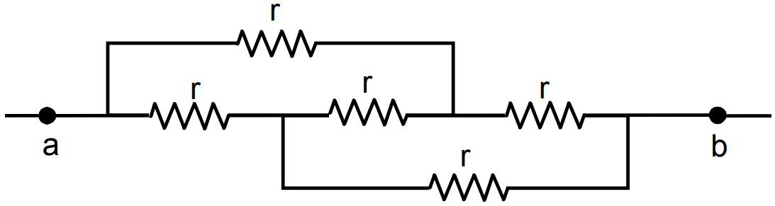
Question 13 Marks
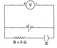
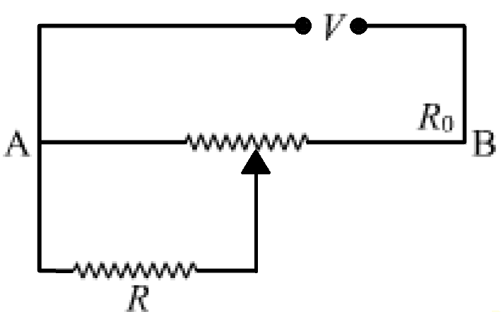
A resistance of R draws current from a potentiometer. The potentiometer wire, AB, has a total resistance of $R_o.$ A voltage V is supplied to the potentiometer. Derive an expression for the voltage across R when the sliding contact is in the middle of potentiometer wire.

Answer
When the slide is in the middle of the potentiometer, only half of its total resistance i.e. $R_02$ (since resistance is directly proportional to length) will be between A and point of contact (C), say $R_1$, will be given by the following expression
$1R_1 = 1R + 1R_02$
$R1 = RR_02R + R_0$
The total resistance between A and B will be sum of the resistance between A & C and C & B ie $R_1 + R_02$
Current flowing through the potentiometer will be
$I = VR_1+ R_02= 2V2R_1+ R_0$
The voltage V_1 taken from the potentiometer will be the product of current I and the resistance R_1
$V_1 = IR_1 = 2V2R_1+ R_0 X R_1 = 2V_2RR_02R + R_0+ R_0\ X\ RR_02R + R_0 = 2VRR_0 + 4R$ View full question & answer→Question 23 Marks
- Three resistors $2\ \Omega,\ 4\ \Omega\ \text{and}\ 5\ \Omega$ are combined in parallel. What is the total resistance of the combination?
- If the combination is connected to a battery of emf 20 V and negligible internal resistance, determine the current through each resistor, and the total current drawn from the battery.
Answer
- Given, three resistors $2\ \Omega,\ 4\ \Omega\ \text{and}\ 5\ \Omega$ are combined in parallel.
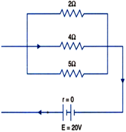
Therefore,
Total resistance of parallel combination,
$\frac{1}{\text{R}}=\frac{1}{\text{R}_1}+\frac{1}{\text{R}_2}+\frac{1}{\text{R}_3}$
$\text{or}\ \ \frac{1}{\text{R}}=\frac{1}{2}+\frac{1}{4}+\frac{1}{5}$
$=\frac{10+5+4}{20}$
$=\frac{19}{20}\ \Omega$
$\text{R}=\frac{20}{19}\ \Omega$
- The combination is connected to a battery of 20 V.
Let the current through resistances $2\ \Omega,\ 4\ \Omega\ \text{and}\ 5\ \Omega\ \text{are}\ \text{l}_1,\ \text{l}_2\ \text{and}\ \text{l}_3$ respectively.
Now, using Ohm's law across each resistor we get,
$\text{I}_1=\frac{\text{V}}{\text{R}_1}=\frac{20}{2}=10\ \text{A}$
$\text{I}_2=\frac{\text{V}}{\text{R}_2}=\frac{20}{4}=5\ \text{A}$
$\text{I}_3=\frac{\text{V}}{\text{R}_3}=\frac{20}{5}=4\ \text{A}$
Hence,
Total current is given by
$\text{I}=\text{I}_1+\text{I}_2+\text{I}_3$
$=10+5+4$
$=19\ \text{A}.$ View full question & answer→Question 33 Marks
Determine the current drawn from a 12 V supply with internal resistance $0.5\ \Omega$ by the infinite network shown in Fig. Each resistor has $1\ \Omega$ resistance.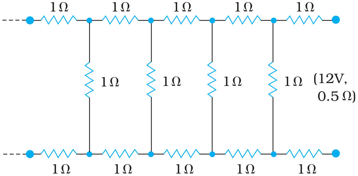
AnswerThe resistance of each resistor connected in the given circuit, $\text{R}=1\ \Omega$
Equivalent resistance of the given circuit = R'
The network is infinite. Hence, equivalent resistance is given by the relation,
$\therefore\ \text{R}'=2+\frac{\text{R}'}{(\text{R}'+1)}$
$(\text{R}')^2-2\text{R}'-2=0$
$\text{R}'= \frac{{2\pm\sqrt{4+8}}}{2}$
$=\frac{2\pm\sqrt{12}}{2}=1\pm\sqrt{3}$
Negative value of R' cannot be accepted. Hence, equivalent resistance,
$\text{R}=(1+\sqrt{3})=1+1.73=2.73\ \Omega$
Internal resistance of the circuit, $\text{r}=0.5\ \Omega$
Hence, total resistance of the given circuit $=2.73+0.5=3.23\ \Omega$
Supply voltage, V = 12 V
According to Ohm’s Law, current drawn from the source is given by the ratio, $\frac{12}{3.23}=3.72\ \text{A}$
View full question & answer→Question 43 Marks
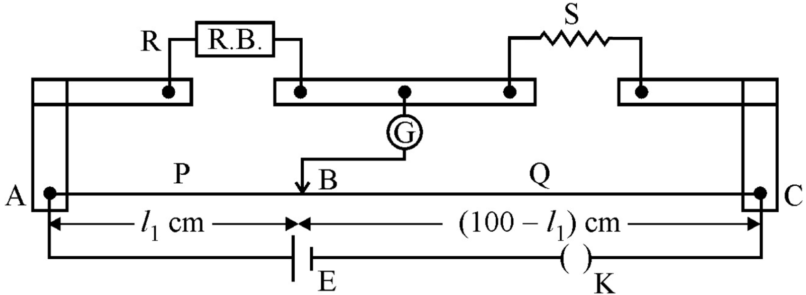
Figure shows a potentiometer circuit for comparison of two resistances. The balance point with a standard resistor $\text{R}=10.0\ \Omega$ is found to be 58.3 cm, while that with the unknown resistance X is 68.5 cm. Determine the value of X. What might you do if you failed to find a balance point with the given cell of emf $\varepsilon?$
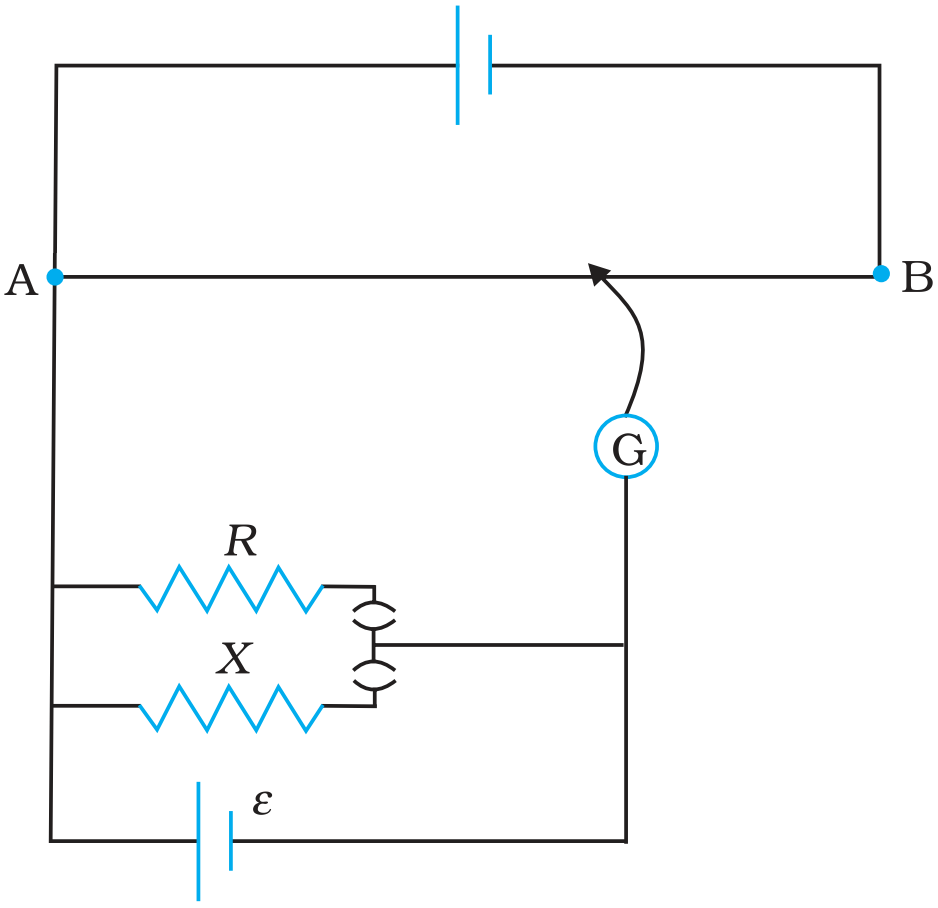
AnswerResistance of the standard resistor, $\text{R}=10.0\ \Omega$
Balance point for this resistance, $l_1 = 58.3 cm$
Current in the potentiometer wire = i
Hence, potential drop across $R, E_1 = iR$
Resistance of the unknown resistor = X
Hence, potential drop across $X, E_2 = iX$
The relation connecting emf and balance point is,
$\frac{\text{E}_1}{\text{E}_2}=\frac{l_1}{l_2}$
$\frac{\text{iR}}{\text{iX}}=\frac{l_1}{l_2}$
$\text{X}=\frac{l_1}{l_2}\times\text{R}$
$=\frac{68.5}{58.3}\times10=11.749\ \Omega$
Therefore, the value of the unknown resistance, $\text{X, is}\ 11.75\ \Omega.$
If we fail to find a balance point with the given cell of emf, ε, then the potential drop across R and X must be reduced by putting a resistance in series with it. Only if the potential drop across R or X is smaller than the potential drop across the potentiometer wire AB, a balance point is obtained.
View full question & answer→Question 53 Marks
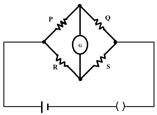
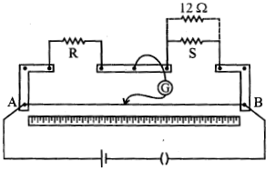
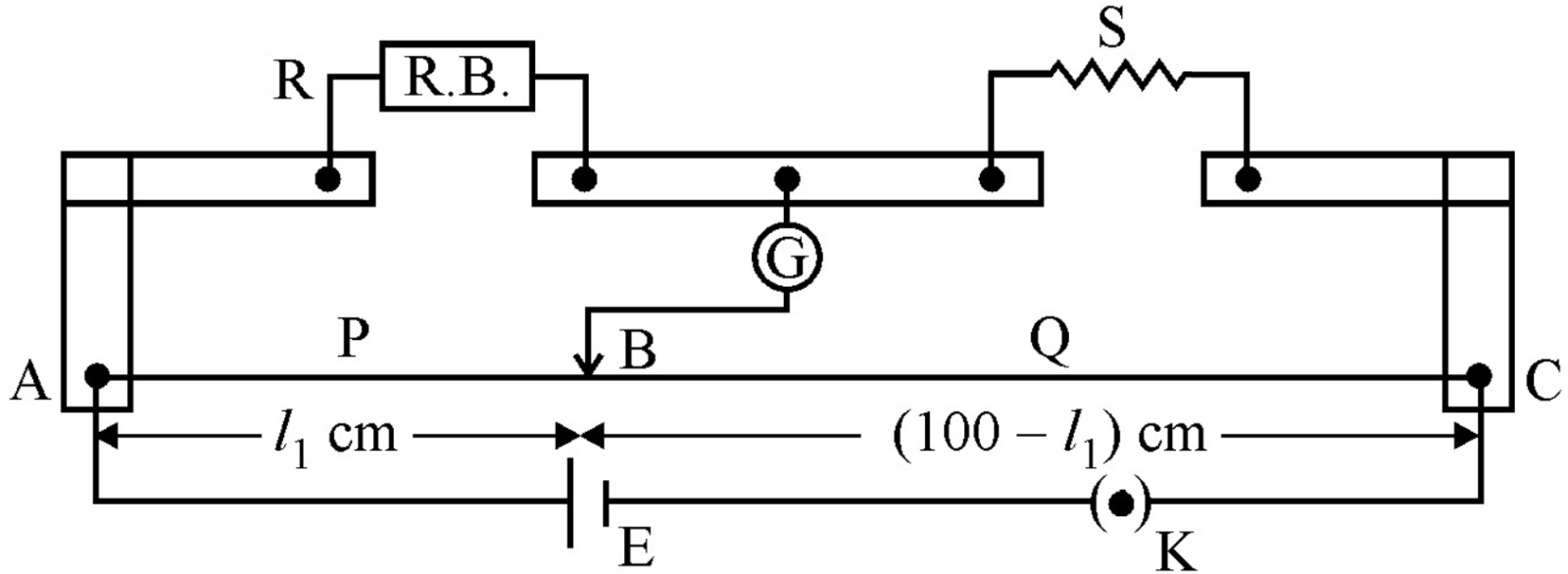
- In a metre bridge [Fig. 3.27], the balance point is found to be at 39.5 cm from the end A, when the resistor Y is of $12.5\ \Omega.$ Determine the resistance of X. Why are the connections between resistors in a Wheatstone or meter bridge made of thick copper strips?
- Determine the balance point of the bridge above if X and Y are interchanged.
- What happens if the galvanometer and cell are interchanged at the balance point of the bridge? Would the galvanometer show any current?
Answer
- Given,
Distance of jockey from end A at the balance point, l = 39.5 cm.
Standard known resistance, $\text{S}=\text{Y}=12.5\ \Omega$
We have to determine the unknown resistance, R = X
Using the relation for balance condition we get,
$\text{S}=\frac{100-1}{1}\times\text{R}$
$\therefore\ \ 12.5=\frac{100-39.5}{39.5}\times\text{X}$
$\text{X}=\frac{12.5\times39.5}{60.5}=8.16\ \Omega$
Thick copper strips helps to minimise resistance of the connections and hence they are used.
- If, X and Y are interchanged,then, lengths are also interchanged.
Therefore, length modifies to, l =100 - 39.5 = 60.5 cm.
- If the galvanometer and cell are interchanged, the position of the balance point remains unchanged. Hence, the galvanometer will show no current.
View full question & answer→Question 63 Marks
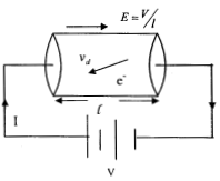
The number density of free electrons in a copper conductor estimated in Example 3.1 is $8.5 \times 10^{28}m^{-3}.$ How long does an electron take to drift from one end of a wire 3.0 m long to its other end? The area of cross-section of the wire is $2.0 \times 10^{-6} m^2$ and it is carrying a current of 3.0 A.
AnswerNumber density of free electrons in a copper conductor, $n = 8.5 \times 10^{28}m^{-3}$Length of the copper wire, $l = 3.0 m$
Area of cross-section of the wire, $A = 2.0 \times 10^{-6} m^2$
Current carried by the wire, I = 3.0 A, which is given by the relation,
$I = nAeV_d$
where,
e = Electric charge $= 1.6 \times 10^{-19} C$
$\text{V}_\text{d}=\text{Drift velocity}=\frac{\text{Length of the wire}}{\text{Times taken to cover}}=\frac{\text{l}}{\text{t}}$
$\text{I}=\text{n Ae}\frac{\text{l}}{\text{t}}$
$\text{I}=\frac{\text{n.A.e.l}}{\text{t}}$
$\text{t}=\frac{\text{n.A.e.l}}{\text{I}}$
$=\frac{3\times8.5\times10^{28}\times2\times10^{-6}\times1.6\times10^{-19}}{3.0}$
$=2.7\times10^4\text{s}$
Therefore, the time taken by an electron to drift from one end of the wire to the other is $2.7\times10^4\text{s}.$
View full question & answer→Question 73 Marks
Given n resistors each of resistance R, how will you combine them to get the (i) maximum (ii) minimum effective resistance? What is the ratio of the maximum to minimum resistance?
AnswerTotal number of resistors = n
Resistance of each resistor = R
- When n resistors are connected in series, effective resistance $R_1$ is the maximum, given by the product nR.
Hence, maximum resistance of the combination, $R_1 = nR$
- When n resistors are connected in parallel, the effective resistance $(R_2) $ is the minimum, given by the ratio $\frac{\text{R}}{\text{n}}.$
Hence, minimum resistance of the combination, $\text{R}_2=\frac{\text{R}}{\text{n}}$
- The ratio of the maximum to the minimum resistance is,
$\frac{\text{R}_1}{\text{R}_2}=\frac{\text{nR}}{\frac{\text{R}}{\text{n}}}=\text{n}^2$ View full question & answer→Question 83 Marks
Three resistors $1\ \Omega,\ 2\ \Omega\ \text{and}\ 3\ \Omega$ are combined in series. What is the total resistance of the combination?
If the combination is connected to a battery of emf 12 V and negligible internal resistance, obtain the potential drop across each resistor.
AnswerGiven, three resistors of resistances $1\ \Omega,\ 2\ \Omega\ \text{and}\ 3\ \Omega$ combined in series.
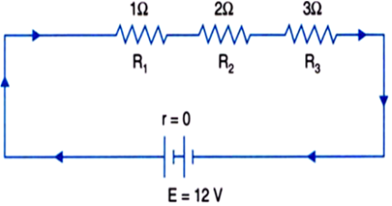
Therefore,
Total resistance of series combination is given by,
$\text{R}=\text{R}_1+\text{R}_2+\text{R}_3$
$=1+2+3$
$=6\ \Omega$
- If the combination is connected to a battery of 12 V and negligible internal resistance.
Current through the circuit,
$\text{I}=\frac{\text{E}}{\text{R}+\text{r}}=\frac{12}{6+0}=2\ \text{A}$
Potential drop across $R_1 = 2 \times 1V = 2V$
Potential drop across $R_2 = 2 \times 2V = 4V$
Potential drop across $R_3 = 2 \times 3V = 6V$ View full question & answer→Question 93 Marks
A storage battery of emf 8.0 V and internal resistance $0.5\ \Omega$ is being charged by a 120 V dc supply using a series resistor of $15.5\ \Omega.$ What is the terminal voltage of the battery during charging? What is the purpose of having a series resistor in the charging circuit?
AnswerEmf of the storage battery, $E = 8.0 V$
Internal resistance of the battery, $\text{r}=0.5\ \Omega$
DC supply voltage, $V = 120 V$
Resistance of the resistor, $\text{R}=15.5\ \Omega$
Effective voltage in the circuit $= V^1$
R is connected to the storage battery in series. Hence, it can be written as
$V^1 = V - E$
$V^1 = 120 - 8 = 112 V$
Current flowing in the circuit = I, which is given by the relation,
$\text{I}=\frac{\text{V}^1}{\text{R}+\text{r}}$
$=\frac{112}{15.5+5}=\frac{112}{16}=7\text{A}$
Voltage across resistor R given by the product, $IR = 7 × 15.5 = 108.5 V$
DC supply voltage = Terminal voltage of battery + Voltage drop across R
Terminal voltage of battery$= 120 - 108.5 = 11.5 V$
A series resistor in a charging circuit Itmtts the current drawn from the external source.
The current will be extremely high in its absence. This is very dangerous.
View full question & answer→Question 103 Marks
The earth’s surface has a negative surface charge density of $10^{-9} Cm^{-2}.$ The potential difference of 400 kV between the top of the atmosphere and the surface results (due to the low conductivity of the lower atmosphere) in a current of only 1800 A over the entire globe. If there were no mechanism of sustaining atmospheric electric field, how much time (roughly) would be required to neutralise the earth’s surface? (This never happens in practice because there is a mechanism to replenish electric charges, namely the continual thunderstorms and lightning in different parts of the globe). (Radius of earth $= 6.37 \times 10^6 m.$)
AnswerSurface charge density of the earth, $\sigma=10^{-9}\ \text{C m}^{-2}$
Current over the entire globe, $\text{I}=1800\ \text{A}$
Radius of the earth, $\text{r}=6.37\times10^6\ \text{m}$
Surface area of the earth,
$\text{A}=4\pi\text{r}^2$
$=4\pi\times(6.37\times10^6)^2$
$=5.09\times10^{14}\ \text{m}^2$
Charge on the earth surface,
$\text{q}=\sigma\times\text{A}$
$=10^{-9}\times5.09\times10^{14}$
$=5.09\times10^{5}\ \text{C}$
Time taken to neutralize the earth's surface = t
$\text{Current},\ \text{I}=\frac{\text{q}}{\text{t}}$
$\text{t}=\frac{\text{q}}{\text{I}}$
$=\frac{5.09\times10^5}{1800}=282.77\text{s}$
Therefore, the time taken to neutralize the earth's surface is 282.77s.
View full question & answer→Question 113 Marks
A heating element using nichrome connected to a 230 V supply draws an initial current of 3.2 A which settles after a few seconds to a steady value of 2.8 A. What is the steady temperature of the heating element if the room temperature is 27.0°C? Temperature coefficient of resistance of nichrome averaged over the temperature range involved is $1.70\times10^{-4}{^\circ\text{C}}^{-1}.$
AnswerHere,
Potential applied across the heating element, V = 230 V
Initial current, $l_1 = 3.2 A$
After few seconds, steady current attained is,$ l_2 = 2.8 A$
Using ohm's law,
$\text{R}_1=\frac{230}{3.2}=71.87\ \Omega$
and,
$\text{R}_2=\frac{230}{2.8}=82.14\ \Omega$
$\alpha=1.7\times10^{-4}{^\circ\text{C}^{-1}}$
$\text{t}_1=27^\circ\text{C}$
Using the relation,
$\text{R}_2=\text{R}_1[1+\alpha(\text{t}_2-\text{t}_1)]$
$\text{Therefore,}\ \ \text{t}_2=\frac{\text{R}_2-\text{R}_1}{\text{R}_1.\alpha}+\text{t}_1$
$\Rightarrow\ \ \text{t}_2=\frac{82.14-71.87}{71.87\times1.7\times10^{-4}}+27$
$=840.56+27$
$=867.56^\circ\text{C}$
$=867^\circ\text{C}$
View full question & answer→Question 123 Marks
- Six lead-acid type of secondary cells each of emf 2.0 V and internal resistance $0.015\Omega$ are joined in series to provide a supply to a resistance of $8.5\ \Omega.$ What are the current drawn from the supply and its terminal voltage?
- A secondary cell after long use has an emf of 1.9 V and a large internal resistance of $380\ \Omega$ What maximum current can be drawn from the cell? Could the cell drive the starting motor of a car?
Answer
- Number of secondary cells, n = 6
Emf of each secondary cell, E = 2.0 V
Internal resistance of each cell, $\text{r}=0.015\ \Omega$
series resistor is connected to the combination of cells.
Resistance of the resistor, $\text{R}=8.5\ \Omega$
Current drawn from the supply = I, which is given by the relation,
$\text{I}=\frac{\text{nE}}{\text{R}+\text{nr}}$
$=\frac{6\times2}{8.5+6\times0.015}$
$=\frac{12}{8.59}=1.39\ \text{A}$
Terminal voltage, V = IR = 1.39 × 8.5 = 11.87 A
Therefore, the current drawn from the supply is 1.39 A and terminal voltage is 11.87 A.
- After a long use, emf of the secondary cell, E = 1.9 V
Internal resistance of the cell, $\text{r}=380\ \Omega$
Hence, maximum current $=\frac{\text{E}}{\text{r}}=\frac{1.9}{380}=0.005\ \text{A}$
Therefore, the maximum current drawn from the cell is 0.005 A. Since a large current is required to start the motor of a car, the cell cannot be used to start a motor. View full question & answer→Question 133 Marks
A battery of emf 10 V and internal resistance $3\ \Omega$ is connected to a resistor. If the current in the circuit is 0.5 A, what is the resistance of the resistor? What is the terminal voltage of the battery when the circuit is closed?
AnswerGiven,
EMF of battery, $\varepsilon=10\ \text{V}$
Internal resistance of battery, $\text{r}=3\ \Omega$
Current flowing in the circuit, $\text{I}=0.5\text{A}$
Using the forlmula $\text{I}=\frac{\varepsilon}{\text{R}+\text{r}}$
$\text{or}\ \ \text{R}=\frac{\varepsilon}{\text{I}}-\text{r}$
where, R is the external resistance.
$\therefore\ \ \text{R}=\frac{10}{0.5}-3=17\ \Omega$ is the required resistance.
Terminal voltage,
$\text{V}=\text{IR}$
$=0.5\times17$
$=8.5\ \text{V}$
View full question & answer→Question 143 Marks
- Derive an expression for drift velocity of free electrons.
- How does drift velocity of electrons in a metallic conductor vary with increase in temperature? Explain.
Answer
- When a potential difference is applied across a conductor, an electric field is produced, and free electrons are acted upon by an electric force $( = - \text{E}e ) .$ Due to this, electrons accelerate and keep colliding with each other and acquire a constant (average) velocity $\text{v}_{d}.$
$\therefore\text{F}_{e} = -\text{Ee}$
$\therefore\text{F}_{e} = \frac{-\text{eV}}{l}$
As $\text{a} = \frac{-\text{F}}{\text{m}} = \frac{- \text{eV}}{\text{m}}$
as v = u+at
u = 0 , $\tau$= (relaxation time)
$\text{v}_{d} = \text{- a }\tau $
$\text{v}_{d} = \frac{ -\text{eV}}{l\text{m}}\tau$
- Decreases, as time of relaxation decreases.
View full question & answer→Question 153 Marks
- The potential difference applied across a given resistor is altered so that the heat produced per second increases by a factor of 9. By what factor does the applied potential difference change?
- In the figure shown, an ammeter A and a resistor of $4\Omega$ are connected to the terminals of the source. The emf of the source is 12 V having an internal resistance of $2\Omega$. Calculate the voltmeter and ammeter readings.
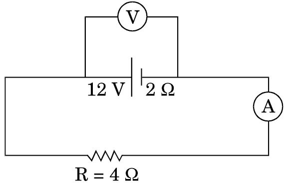
Answer
- $H=\frac{V^2}{R}$
$\therefore$ V increases by a factor of $\sqrt{9}=3$
- Ammeter Reading $I=\frac{V}{R+r}$
$=\frac{12}{4+2}A=2A$
Voltmeter Reading $V=E-Ir$
$=[12-(2\times2)]\text{ }\text{V}=8\text{V}$ View full question & answer→Question 163 Marks
Answer the following:
- Why are the connections between the resistors in a meter bridge made of thick copper strips?
- Why is it generally preferred to obtain the balance point in the middle of the meter bridge wire?
- Which material is used for the meter bridge wire and why?
Answer
- This is to ensure that the connections do not contribute any extra, unknown, resistances in the circuit.
- This is done to minimize the percentage error in the value of the unknown resistance.
Alternate Answer
This is done to have a better “ Balancing out” of the effects of any irregularity or non-uniformity in the metre bridge wire.
Alternate Answer
This can help in increasing the senstivity of the metre bridge circuit.
- Manganian/constantan/Nichrome. This material has a low temperature of coefficient of resistance/high reisistivity.
View full question & answer→Question 173 Marks
A resistance of R $\Omega$ draws current from a potentiometer as shown in the figure. The potentiometer has a total resistance $R_oΩ.$ A voltage V is supplied to the potentiometer. Derive an expression for the voltage across R when the sliding contact is in the middle of the potentiometer.
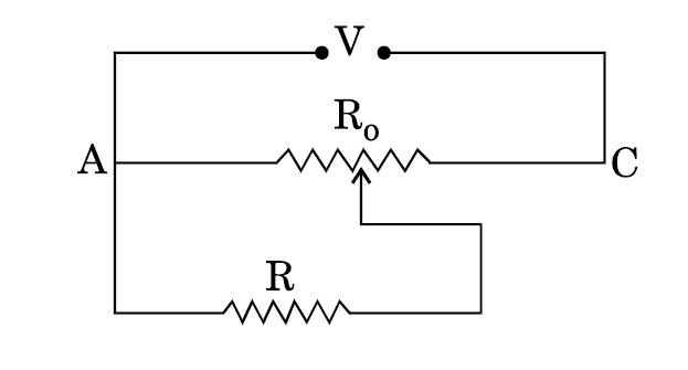
Answer$\text{R}_{total} = \frac{\text{R}_{o}}{2} + \frac{\frac{\text{R}_{o}}{2}.\text{R}}{\frac{\text{R}_{o}}{2} + \text{R}}$
$ = \frac{\text{R}(\text{R}_{o} + 4\text{R})}{2(\text{R}_{o} + 2 \text{R})}$
$\text{I}_{(total)} = \frac{\text{V}}{\text{R}_{total}}$
Current through $R = I_2 = \text{I}_{total}\text{ x}\frac{\frac{\text{R}_{o}}{2}}{\frac{\text{R}_{o}}{2}+\text{R}}$
$ = \text{I}_{total}\text{ x}\frac{\text{R}_{o}}{\text{R}_{o} + 2 \text{R}}$
$ = \frac{\text{V}.2(\text{R}_{o} + 2 \text{R})}{\text{R}(\text{R}_{o} + 4\text{R})}\text{x}\frac{\text{R}_{o}}{\text{R}_{o} + 2 \text{R}}$
$ = \frac{2\text{VR}_{o}}{\text{R}(\text{R}_{o} + 4 \text{R})}$
Voltage across $R = I_2 R = \bigg(\frac{2\text{VR}_{o}}{\text{R}_{o} + 4 \text{R}}\bigg).$
View full question & answer→Question 183 Marks
A potential difference V is applied across a conductor of length L and diameter D. How is the drift velocity, $V_d,$ of charge carriers in the conductor affected when (i) V is halved, (ii) L is doubled and (iii) D is halved? Justify your answer in each case.
Answer
- Drift velocity will become half as $\text{v}_{d}\propto\text{V}.$
- Drift velocity will become half as $\text{v}_{d}\propto\text{V}.$
- Drift velocity will remain the same as $V_d$ is independent of diameter (D).
View full question & answer→Question 193 Marks
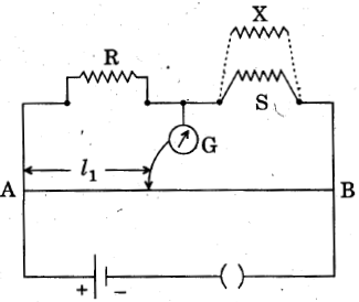
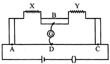
- Write the principle of working of a metre bridge.
- In a metre bridge, the balance point is found at a distance $l_1$ with resistances R and S as shown in the figure.
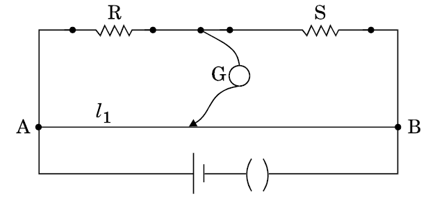
An unknown resistance X is now connected in parallel to the resistance S and the balance point is found at a distance $l_2$. Obtain a formula for X in terms of $l_1$, $l_2$ and S.Answer
- The principle of working of a meter bridge is same as that of a balanced Wheatstone bridge.
Alternatively:
When $\text{i}_{\text{g}}=0$, then $\frac{P}{Q}=\frac{R}{S}$
- $\frac{R}{S}=\frac{l_1}{100-l_1}$
When X is connected in parallel:
$\frac{R}{\Big(\frac{XS}{X+S}\Big)}=\frac{l_2}{100-l_2}$
On solving, we get $X=\frac{l_1S(100-l_2)}{100(l_2-l_1)}$ View full question & answer→Question 203 Marks
A wire AB is carrying a steady current of 12 A and is lying on the table. Another wire CD carrying 5A is held directly above AB at a height of 1 mm. Find the mass per unit length of the wire CD so that it remains suspended at its position when left free. Give the direction of the current flowing in CD with respect to that in AB. $[$Take the value of $g = 10 ms^{–2}]$
Answer
Concepts:
- Current carrying conductors repel each other, if current flows in the opposite direction.
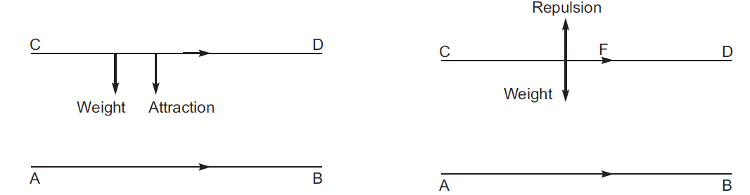
- Attract each other if current flows in the same direction.
If wire CD remain suspended above AB then
$F_{repulsion} =$Weight
$\frac{\mu_{0}\text{I}_{1}\text{I}_{2}l}{2\pi\text{r}} = \text{mg}$
where r = Separation between the wires
$\frac{\text{m}}{l} = \frac{\mu_{0}\text{I}_{1}\text{I}_{2}}{2\pi\text{rg}}$
$ = \frac{2\times10^{-7}\times12\times5}{1\times10^{-3}\times10}$
$=1.2\times10^{–3} \text{kg/m}$
Current in CD should be in opposite direction to that in AB. View full question & answer→Question 213 Marks
Define relaxation time of the free electrons drifting in a conductor. How is it related to the drift velocity of free electrons? Use this relation to deduce the expression for the electrical resistivity of the material.
AnswerRelaxation time$(\tau)$: The average time interval between two successive collisions. For the free electrons drifting within a conductor (due to the action of the applied electric field), is called relaxation time.
Relation
$\text{V}_{d} = ( - \text{e E } \tau) / \text{m}$
Since $i = - n\ e\ A\ v_d$
n $ e^2\ A\ \tau$V / m l
$\therefore\text{V}/ \text{i} = \text{ml}/(\text{ne}^{2}\text{A}\tau) = \rho\text{ l } / \text{A}$
$\therefore\rho = \text{m}/ (\text{n e}^{2}\tau). $
View full question & answer→Question 223 Marks
Calculate the value of the resistance R in the circuit shown in the figure so that the current in the circuit is 0.2A. What would be the potential difference between points Band E?
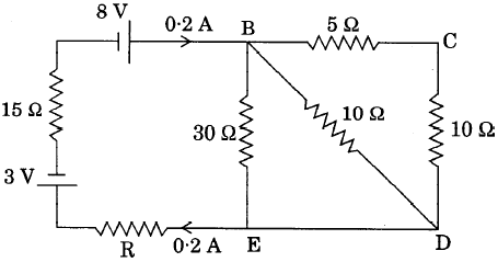
Answer$R_{BCD} = 15\Omega$
$\frac{1}{\text{R}_{BE}} = \frac{1}{15} + \frac{1}{10} + \frac{1}{30}$
$ = \frac{2+ 3 + 1 }{30}$
$\text{R}_{BE} = 5 \Omega$
$(15+5+R) × 0.2 = 8-3= 5$
$(20+R) = 25$
R = 5 $\Omega$
$\therefore\text{V}_{BE} = \text{IR}_{BE}$
$ = 0.2\times5 = 1.0 \text{V}.$
View full question & answer→Question 233 Marks
Two heating elements of resistances $R_1$ and $R_2$ when operated at a constant supply of voltage, V, Consume power $P_1$ and $P_2 $ respectively. Deduce the expressions for the power of their combination when they are, in turn, connected in (i) series and (ii) parallel across the same voltage supply.
Answer$P_1=\frac{V^2}{R_1}\\P_2=\frac{V^2}{R_2}\\\text{In Series}\\P=\frac{V^2}{{R_1}+{R_2}}\\\text{Alternatively}\\p=\frac{V^2}{V^2\bigg(\frac{1}{p_1}+\frac{1}{p_2}\bigg)}\\\frac{1}{p }=\frac{1}{p_1 }+\frac{1}{p_2 }\\\text{In Parallel}\\P=\frac{V^2(R_1+R_2)}{R_1+R_2}\\\text{Alternatively}\\P=\frac{V^2}{R}=\frac{V^2(P_1+P_2)}{V^2}\\P=P_1+P_2 $
View full question & answer→Question 243 Marks
State Kirchhoff’s rules. Use these rules to write the expressions for the currents $I_1, I_2$ and $I_3$ in the circuit diagram shown.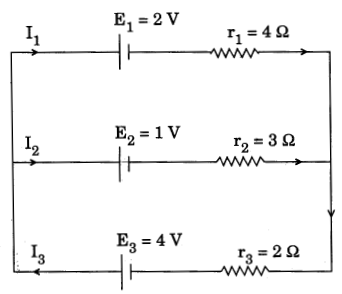
Answer
- Junction rule: At any junction, the sum of the currents entering the junction is equal to the sum of currents leaving the junction.
- Loop rule: The algebraic sum of changes in potential, around any closed loop, involving resistors and cells in the loop, is zero.
Expressions for the currents $I_1, I_2$ and $I_3$ using given loop.
- $I_3 = I_2 + I_1$
- $4I_1 – 3I_2 + 1 = 0$
- $3I_2 + 2I_3 – 3 = 0.$
View full question & answer→Question 253 Marks
Write any two factors on which internal resistance of a cell depends. The reading on a high resistance voltmeter, when a cell is connected across it, is 2.2 V. When the terminals of the cell are also connected to a resistance of 5 Ω as shown in the circuit, the voltmeter reading drops to 1.8 V. Find the internal resistance of the cell.
Answer
- Nature of electrolyte.
- Temperature of electrolyte.
- Area of electrode.
- Concentration of electrolyte.
- Distance of separation between the electrodes.
Calculation of internal resistance:
Given $\text{E} = 2.2\text{V};\text{R} = 5 \Omega\text{ and }\text{V} = 1.8\text{V}$
$\therefore\text{I} = \frac{\text{V}}{\text{R}} = \frac{1.8}{5} = 0.36$
$\text{V} = \text{E} - \text{Ir}$
$\Rightarrow\text{r} = \frac{\text{E - V }}{\text{I}} = \frac{2.2 - 1.8}{0.36} = \frac{10}{9} = 1.1\Omega$
Alternate Answer
$\text{r} = \bigg(\frac{\text{E - V}}{\text{V}}\bigg)\times\text{R}$
$ = \bigg(\frac{2.2 - 1.8}{1.8}\bigg)\times5$
$ = 1.1\Omega.$ View full question & answer→Question 263 Marks
- State the principle of working of a meter bridge.
- In a meter bridge balance point is found at a distance $l_1$ with resistances R and S as shown in the figure.
When an unknown resistance X is connected in parallel with the resistance S, the balance point shifts to a distance $l_2$. Find the expression for X in terms of $l_1, l_2$ and S.Answer
- Metre bridge works on the principle of the Wheatstone bridge.
- In first case $\frac{\text{R}}{\text{S}} = \frac{\ell_{1}}{(100 - \ell_{1})}$
In second case $\frac{\text{R}}{\bigg(\frac{\text{XS}}{\text{X} + \text{S}}\bigg)} = \frac{\ell_{2}}{100 - \ell_{2}}$
$\Rightarrow\text{X} = \text{S}\bigg[\frac{\ell_{2}}{\ell_{1}}\bigg(\frac{100 - \ell_{1}}{100 - \ell_{2}}\bigg) - 1\bigg]^{-1}.$ View full question & answer→Question 273 Marks
- Calculate the equivalent resistance of the given electrical network between points A and B.
- Also calculate the current through CD and ACB, if a 10 V d.c. source is connected between A and B, and the value of R is assumed as 2 Ω.

Answer
- Circuit:

Calculation of $\frac{1}{\text{R}_{AB}} = \frac{1}{2\text{R}} + \frac{1}{2\text{R}}\text{ or }\text{R}_{AB} = \text{R}$
- Current through CD = 0
Current through ACB = $\frac{10\text{V}}{4\Omega} = 2.5\text{A}.$ View full question & answer→Question 283 Marks
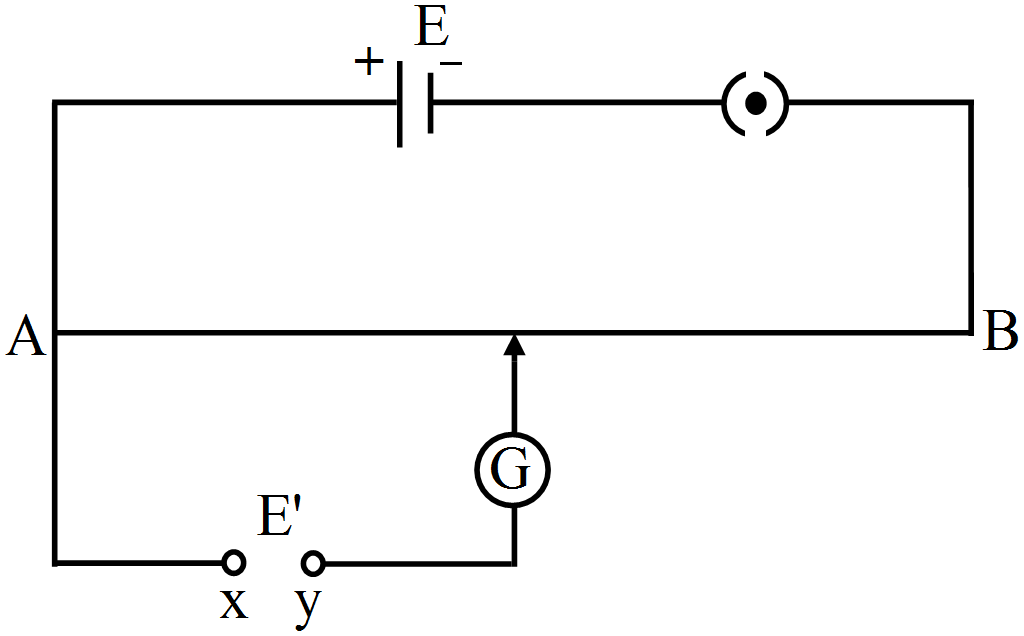
For the potentiometer circuit shown in the given figure, points X and Y reprensent the two terminals of an unknown emf E'. A student observed that when the jockey in moved from the end A to the end B of the potentiometer wire, the deflection in the galvanometer remains in the same direction.

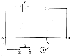
What may be the two possible faults in the circuit that could result in this obsevation?
If the galvanometer deflection at the end B is (i) more, (ii) less, than that at the end A, which of the two faults, listed above, would be there in the circuit?
Give reasons in support of your answer in each case.
AnswerPossible Faults
- The negative terminal of E' is connected to point X.
- |E'| > |E'|
(i) If galvanometer shows more defection at B
Cause: Negative terminal of E' is connected to X
Reason : Potential difference across wire and the cell E' send current through the galvanometer in the same sense and the galvanometer deflection increases with an increase in the length of the wire. (iii) If galvanometer shows less deflection at B
Cause: |E'| > |E|
Reason: Potential difference across the potentiometer wire opposes E' and current in galvanometer decreases with an increase in the length of the wire.
View full question & answer→Question 293 Marks
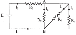
The given figure shows a network of resistances $R_1, R_2, R_3$ and $R_4.$
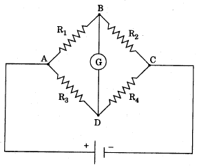
Using Kirchhoff's laws, establish the balance condition for the network. Answer
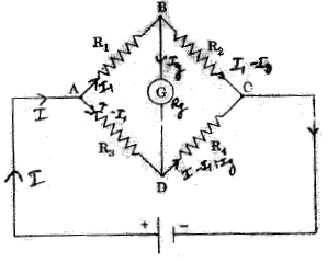 Loop Equations
(Loop ABDA) $– I_1R_1 – IgRg + (I – I_1)R_3=0$
(Loop BCDB)$ – ( I_1 – Ig ) R_2 + (I – I_1 + Ig ) R_4 + Ig\ Rg =0$
Derivation of Result
as $ Ig=0, I_1R_1= (I –I_1) R_3$
$I_1 R_2= (I – I_1) R_4$
$\frac{\text{R}_{1}}{\text{R}_{2}} =\frac{\text{R}_{3}}{\text{R}_{4}}$. View full question & answer→Question 303 Marks
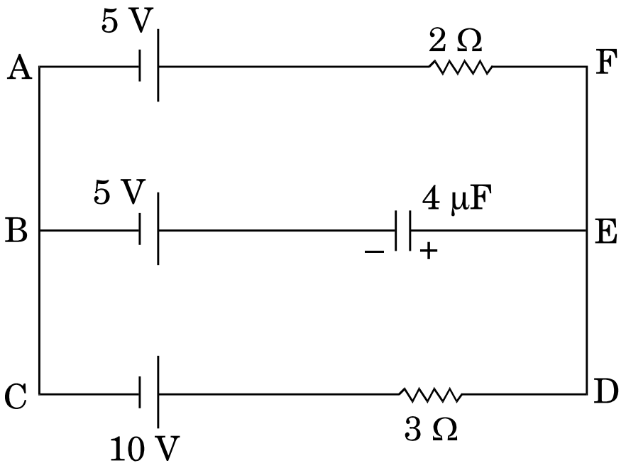
In the given circuit, with steady current, calculate the potential drop across the capacitor and the charge stored in it.

Answer
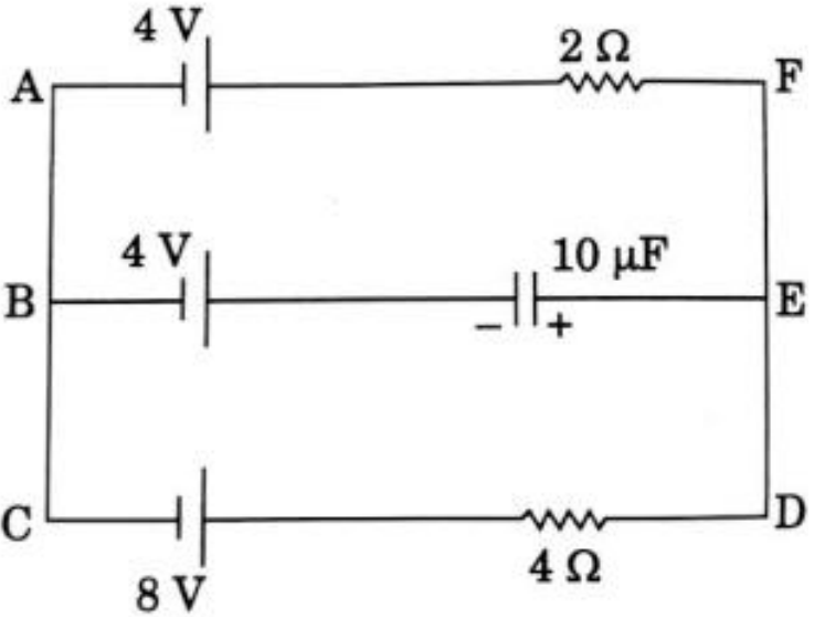 In loop ACDFA
$I=\bigg[\frac{8-4}{4+2}\bigg]\text{A}=\frac{2}{3}\text{A}$
$V_{AF}=V_{BE}$
$\Rightarrow\text{ }4-2\times\frac{2}{3}=4-V_c$
$\Rightarrow\text{ }V_c=\frac{4}{3}\text{V}$
$\text{Charge}, \text{Q}=CV_c$
$\text{Q}=(10{\mu}\text{F}\times\frac{4}{3})$
$=13.33 \text{ }{\mu}\text{C}$ View full question & answer→Question 313 Marks
In the given circuit, with steady current, calculate the potential drop across the capacitor in terms of V.
Answer
 In steady state branch BE is eliminated
$ \text{I}=\frac{10{\text{V}}-5\text{V}}{(3+2){\Omega}}\text{A}$
$=\text{1A}$
For loop EBCDE
$-v_c{-5+10-3\times1}=0$
$-{\text{V}}_c+10-8=0$
$\therefore{\text{V}_c}=2\text{ }\text{volt}$ View full question & answer→Question 323 Marks
In the given circuit, with steady current, calculate the potential difference across the capacitor and the charge stored in it.

Answer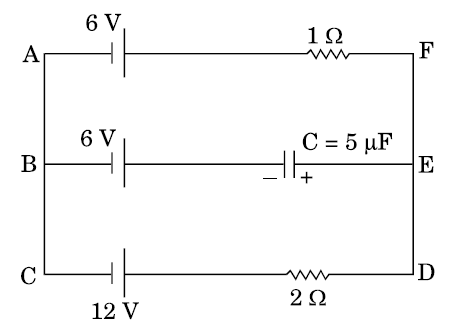
In loop ACDFA
$I=\frac{12-6}{(1+2)}=2\text{A}$
$\text{V}_{AF}=\text{V}_{BE}$
$\Longrightarrow 6+2=6+\text{V}_c$
$\Longrightarrow\text{V}_c=2\text{V}$
$\text{Charge Q = C}V_c=5\mu F\times2V=10\mu C$ View full question & answer→Question 333 Marks
A potentiometer wire of length 1 m has a resistance of 5 $\Omega$. It is connected to a 8 V battery in series with a resistance of 15 $\Omega$. Determine the emf of the primary cell which gives a balance point at 60 cm.
AnswerCurrent flowing in the potentiometer $\text{I} = \frac{\text{V}}{\text{R} + \text{R}'}$ $=\frac{8.0}{5+15}A=0.4 \ A$ Potential drop across the potentiometer wire V = IR
= 0.4 x 10 V = 2.0 V $K=\frac{V}{l}=\frac{2.0}{1.0}=2.0 \text{ V/m}$Unknown emf $\text{E}=Kl'$
= 2.0 x 0.6 V
= 1.2 V.
View full question & answer→Question 343 Marks
A resistance of R draws current from a potentiometer. The potentiometer wire, AB, has a total resistance of $R_o.$ A voltage V is supplied to the potentiometer. Derive an expression for the voltage across R when the sliding contact is in the middle of potentiometer wire.
Answer
When the slide is in the middle of the potentiometer, only half of its total resistance
i.e. $R_02$ (since resistance is directly proportional to length) will be between A and point of contact (C), say
$R_1,$ will be given by the following expression
$1R_1 = 1R + 1R_02 R1 = RR_02R + R_0$
The total resistance between A and B will be sum of the resistance between A & C and C & B
ie $R_1 + R_02$ Current flowing through the potentiometer will be
$I = VR_1+ R_02= 2V2R_1+ R_0$
The voltage V_1 taken from the potentiometer will be the product of current I and the resistance
$R_1V_1 = IR_1 = 2V2R_1+ R_0 X R_1$
$= 2V_2RR_02R + R_0+ R_0 X RR_02R + R_0$
$= 2VRR_0 + 4R$ View full question & answer→Question 353 Marks
A potentiometer wire of length 1.0 m has a resistance of l5 $\Omega$. It is connected to a 5 V battery in series with a resistance of 5 $\Omega$ Determine the emf of the primary cell which gives a balance point at 60 cm.
Answer$ \text{I}=\frac{V}{\text{R+R}^{'}}$
$=\frac{5}{5+15}\text{A}=0.25\ \text{A}$
Potential drop across the potentiometer wire
V = IR
= 0.25 x 15 V= 3.75 volt
Potential Gradient k = V/ $\ell$ = 3.75 V/ 1.0 m = 3.75 V/m
$\therefore$ unknown emf (E) of the cell = $\text{kl}{'}$
= 3.75 x 0.6 V
= 2.25 volt.
View full question & answer→Question 363 Marks
A cell of emf 'E' and internal resistance 'r' is connected across a variable load resistor R. Draw the plots of the terminal voltage V versus (i) R and (ii) the current I.
It is found that when R = 4$\Omega$, the current is 1 A and when R is increased to 9$\Omega$, the current reduces to 0.5 A. Find the values of the emf E and internal resistance r.
Answer
 $\text{I} = \frac{\text{E}}{\text{R} +\text{r}}$
$1 = \frac{\text{E}}{4 + \text{r}}$
$ = >\text{E} = 4 +\text{r}$ ..... (i)
Also,
$0.5 =\frac{\text{E}}{9+ \text{r}}$
E = 4.5+ 0.5 r ..... (ii)
From equation (i) & (ii)
4 + r = 4.5 + 0.5
$\therefore\text{r} = 1\Omega$
Using this value of r, we get.
E = 5V. View full question & answer→Question 373 Marks
A potentiometer wire of length 1 m has a resistance of 10$\Omega$. It is connected to a 6 V battery in series with a resistance of 5$\Omega$. Determine the emf of the primary cell which gives a balance point at 40 cm.
AnswerCurrent flowing in Potentiometer wire,
$\text{I} = \frac{\text{V}}{\text{R} + \text{R}'}$
$ = \frac{6}{10 +5 }\text{A} = 0.4\text{A}$
Potential drop across the potentiometer wire
V = IR
= 0.4 x 10 V = 4.0 V
Potential Gradient k = $\text{V}/ \ell$= 4.0 V/m
$\therefore\text{unknown emf of the cell (E) = K}\ell$
= 4.0 x 0.4 V
= 1.6 V.
View full question & answer→Question 383 Marks
In the figure a long uniform potentiometer wireABis having a constant potential gradient along its length. The null points for the two primary cells of emfs $\varepsilon_{1}$ and $\varepsilon_{2}$
connected in the manner shown are obtained at a distance of 120 cm and 300 cm from the end A. Find (i) $\varepsilon_{1}$/$\varepsilon_{2}$and (ii) position of null point for the cell $\varepsilon_{1}$. How is the sensitivity of a potentiometer increased?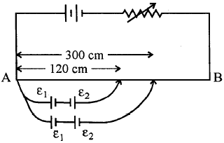
Using Kirchoffs rules determine the value of unknown resistance R in the circuit so that no current flows through 4 $\Omega$ resistance.Also find the potential difference between A and D.
Answer
- $\varepsilon_{1} + \varepsilon_{2}$ = 300k (k is potential gradient in volt/cm)
$\varepsilon_{1} - \varepsilon_{2} = 120 \text{k}$
$\Rightarrow\frac{\varepsilon_{1}}{\varepsilon_{2}} = 7 / 3$
- $\varepsilon_{1} + \varepsilon_{2} = 300\text{k}$
$\therefore\varepsilon_{1} + \frac{3}{7}\varepsilon_{1} = 300 \text{k}$
$\Rightarrow\varepsilon_{1} = 210 \text{k}$
Therefore, balancing length for cell $\varepsilon_{1}$ is 210cm.
- By decreasing potential gradient.
[Or through Increasing length, reducing potential drop across wire, increasing resistance put in series with the main cell etc.]
Alternate Answer
Applying Kirchhoff's Voltage rule
for loop ABEFA
-9 + 6 + 4 x 0 +2 I = 0
2 I – 3 = 0
$\text{I} =\frac{3}{2}\text{A} = 1.5\text{A}$
For loop BCDEB
3 + I R + 4 x 0– 6 = 0
$\therefore\text{IR} = 3 $
Substituting the value of current I,
$\frac{3}{2}\times\text{R} = 3 $
$\therefore\text{R} = 2\Omega$
Potential difference between A & D
Through path ABCD
$+9V – 3V – IR = V_{AD}$
$ + 9 - 3 - \frac{3}{2}\times2 = \text{V}_{AD}$
$\Rightarrow\text{V}_{AD} = 3\text{V}$
Alternate Answer
through path AFD
$\frac{3}{2}\times2 =\text{V}_{AD}$
$\Rightarrow\text{V}_{AD} = 3 \text{V}.$ View full question & answer→Question 393 Marks
Define the terms (i) drift velocity, (ii) relaxation time.
A conductor of length L is connected to a dc source of emf ε. If this conductor is replaced by another conductor of same material and same area of cross-section but of length 3L, how will the drift velocity change?
AnswerDrift velocity: The average velocity with which the free electrons drift under the influence of an external field.
RelaxationTime: Average time interval between two successive collisions of an electron with the ions/atoms of the conductor.
The drift velocity will be inversely proportional to 1 $( \text {or }\text{v}_{d}\propto\frac{1}{l})$ and hence it will become one third of its initial value.
Alternate Answer
$\text{V}'_{d} = \frac{\text{V}_{d}}{3}.$
View full question & answer→Question 403 Marks
In the circuit shown, $R_1 = 4Ω, R_2 = R_3 = 15Ω, R_4 = 30Ω$ and E = 10V. Calculate. The equivalent resistance of the circuit and the current in each resistor.
Answer$R_2, R_3$ and $R_4$ are in parallel.
$\frac{1}{\text{R}_{234}} = \frac{1}{15} + \frac{1}{30} + \frac{1}{15} = \frac{2+1+2}{30} = \frac{5}{30}$
$\Rightarrow\text{R}_{234} = 6 \Omega$
Now $R_{234}$ is in series with $R_1,$ so $ R_{eq} = 4 \Omega$+ 6 $\Omega$= 10 $\Omega$
$\therefore\text{I} = \frac{\text{E}}{\text{R}_{eq}} = \frac{10}{10}\text{A} = 1\text{A}$
$\therefore\text{I}_{1} = 1 \text{A}$
$\therefore\text{ Current through } \text{R}_{1} = 1 \text{A}$
P.D. across $\text{R}_{1} = 4 \text{V}$
So, P.D. across $R_{234} = 6\ V$
$\therefore\text{I}_{2}\text{R}_{2} = \text{I}_{4}\text{R}_{4} = \text{I}_{3}\text{R}_{3} = 6 \text{V}$
$\text{I}_{2} = \frac{6}{15}\text{A} = 0.4 \text{A}$
$\text{I}_{3} = \frac{6}{15}\text{A} = 0.4\text{A}$
$\text{I}_{4} = \frac{6}{30}\text{A} = 0.2\text{A}.$
View full question & answer→Question 413 Marks
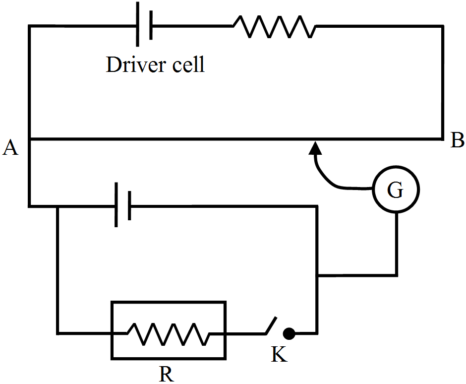
Write the principle of working of a potentiometer. Describe briefly, with the help of a circuit diagram, how a potentiometer is used to determine the internal resistance of a given cell.
AnswerWorking principle: When constant current flows through a wire of uniform cross section, then potential difference across the wire is directly proportional to the length. $\text{V}\propto l$
With key $K_2$ open, balance is obtained at length $l_1 (AN_1).$ Then, $\varepsilon = \Phi l_{1}(\Phi = \text{ potential gradient)}$ When key $K_2$ is closed, the cell sends a current (I) through the resistance box (R). If V is the terminal potential difference of the cell and balance is obtained at length $l_2 (AN_2), $ $\text{V} = \Phi l_{2}$ But $\frac{\varepsilon}{\text{V}} = \frac{\text{I}(\text{R} + \text{r})}{\text{IR}} = \bigg(1 + \frac{\text{r}}{\text{R}}\bigg)$ $\therefore\bigg(1 + \frac{\text{r}}{\text{R}}\bigg) = \frac{l_{1}}{l_{2}}$ $\Rightarrow\text{r} = \frac{(l_{1} - l_{2})}{l_{2}}\text{R}.$ View full question & answer→Question 423 Marks
In a meter bridge, the null point is found at a distance of 40 cm from A. If a resistance of 12 Ω is connected in parallel with S, the null point occurs at 50.0 cm from. Determine the values of R and S.
Answer$\frac{\text{R}}{\text{S}} = \frac{40}{60} = \frac{2}{3}$
$\frac{\text{R}(12 + \text{S})}{12\text{S}} = \frac{50}{50} = 1 $
$\Rightarrow\text{R} = 4 \Omega \text { and }\text{S} = 6 \Omega.$
View full question & answer→Question 433 Marks

The figure shows experimental set up of a meter bridge. When the two unknown resistances X and Y are inserted, the null point D is obtained 40 cm from the end A. When a resistance of 10 Ω is connected in series with X, the null point shifts by 10 cm. Find the position of the null point when the 10 Ω resistance is instead connected in series with resistance ‘Y’. Determine the values of the resistances X and Y.
Answer$\frac{X}{Y} =\frac{40}{60}\Rightarrow\text{X} = \frac{2}{3}\text{Y} $......................................(i}$\frac{\text{X} + 10}{\text{Y}} = \frac{50}{50}$....................................................(ii)
$\Rightarrow\text{X} +10 = \text{Y}$
From (i) and (ii)
$\frac{2}{3}\text{Y}+ 10 =\text{Y} $ $\Rightarrow \text{Y} = 30\Omega$
As $\text{X} =\frac{2}{3}\text{Y}$ $\Rightarrow 20 \Omega$
When 10Ω resistor is connected in series with resistor Y, we have
$\frac{\text{X}}{\text{Y} +10} = \frac{l}{100 - l}$ $\Rightarrow \frac{20}{40} = \frac{l}{10 - l}$
$\Rightarrow2l = 100 - l$
$3l = 100$
$l = \frac{100}{3} = 33.33\text{cm }$.
View full question & answer→Question 443 Marks
A potentiometer wire of length 1 m is connected to a driver cell of emf 3 V as shown in the figure. When a cell of 1.5 V emf is used in the secondary circuit, the balance point is found to be 60 cm. On replacing this cell and using a cell of unknown emf, the balance point shifts to 80 cm.
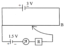
- Calculate unknown emf of the cell.
- Explain with reason, whether the circuit works, if the driver cell is replaced with a cell of emf 1 V.
- Does the high resistance R, used in the secondary circuit affect the balance point? Justify your answer.
Answer
- $\frac{E_1}{E_2} = \frac{l_1}{l_2}$
$\therefore \text{E}_{2} = \frac{E_1\ell_2}{\ell_2} = 2\nu$
- No. P.D. across wire AB will not be able to balance 1.5V emf/balance point will not exist on the wire AB.
- No. At balance point no current is drawn from the cell. Balance point is independent of R.
View full question & answer→Question 453 Marks
A number of identical cells,
n, each of emf
E, internal resistance
r connected in series are charged by a d.c. source of emf
E', using a resistor
R.
- Draw the circuit arrangement.
- Deduce the expressions for (a) the charging current and (b) the potential difference across the combination of the cells.
Answer
-
- .
- $\text{I (nr + R) = }\varepsilon' - \text{n}\varepsilon$
$\therefore \text{I}= \frac{\varepsilon'- \text{n}\varepsilon}{\text{R + nr}}$
- $\text{V} = \text{N}\varepsilon + \text{Inr}.$
View full question & answer→Question 463 Marks
Prove that the current density of a metallic conductor is directly proportional to the drift speed of electrons.
AnswerTotal number of free electrons, N = n A.
$\therefore$ Total Charge $Q = N\ e$
$= nAel$
$\tau = \frac{1}{\text{v}_{d}}$
$\therefore$ $\text{I} = \frac{Q}{\tau} = \frac{\text{nAel}}{l}\text{v}_{d} $
$= nAev_d$
J = current dencity $= \frac{\text{I}}{\text{A}}$
$\therefore$ $\text{J} = \frac{nAev_d}{A} = \text{nev}_{d}$
$\therefore$ $\text{J} \propto \text{V}_{d}$ View full question & answer→Question 473 Marks
State Kirchhoff's rules of current distribution in an electrical network. Using these rules determine the value of the current I1 in the electric circuit given below.
AnswerJunction Rule: At any junction of several circuit elements the sum of currents entering the junction must be equal to the sum of currents leaving it.Loop Rule: Algebraic sum of changes in the potential around any closed loop must be zero.
Loop ABCFA
$\text{I}_{1} + 2\text{I}_{3} = 2 ........................$ (1)
Loop FCDEF
$2\text{I}_{3} + \text{I}_{2} = 6 .................................$(2)
At F, $\text{I}_{1} + \text{I}_{2} = \text{I}_{3} ........................................$(3)
Solving (1), (2) and (3)
$\text{I}_{1} = - 0.8 \text{A}$ View full question & answer→Question 483 Marks
Write the mathematical relation for the resistivity of a material in terms of relaxation time, number density and mass and charge of charge carriers in it. Explain, using this relation, why the resistivity of a metal increases and that of a semi-conductor decreases with rise in temperature.
Answer$\rho = \frac{\text{m}}{\text{ne}^{2}\iota}$For a metal, as the temperature increases,$\iota$decreases. Hence $\rho$increases. For a semiconductor, as the temperature increases, number density of electrons in the conduction band increases. Hence $\rho$ decreases.
View full question & answer→Question 493 Marks
A 10 m long wire of uniform cross-section and 20 $\Omega$ resistance is used in a potentiometer. The wire is connected in series with a battery of 5V along with an external resistance of 480 $\Omega$. If an unknown emf E is balanced at 6.0 m length of the wire, calculate:
- The potential gradient of the potentiometer wire.
- The value of unknown emf E.
AnswerCurrent I $= \frac{5}{480+20}= 0.01\text{A}$$\therefore $ p.d.across the wire (dV) = IR = 0.1X20=0.2V
Potental gradient $\big(\triangle\text{V}\big)\frac{\text{dV}}{\text{dx}}= \frac{0.2}{10}\frac{\text{V}}{m}=0.02\text{Vm}^{-1}$
E.M.F. Of the cell $\varepsilon= \bigtriangleup\text{V}\times$ balance lentgh
=0.02X6 = 0.12 V
View full question & answer→Question 503 Marks
- Define the term ‘conductivity’ of a metallic wire. Write its SI unit.
- Using the concept of free electrons in a conductor, derive the expression for the conductivity of a wire in terms of number density and relaxation time. Hence obtain the relation between current density and the applied electric field E.
Answer
- Conductivity of a metallic wire is defined as the conductance (reciprocal of resistance) of a metallic wire of unit side and unit cross sectional area perpendicular to the current flow.
Alternate Answer
Conductivity is defined as the reciprocal of resistvity of a metallic wire.
S.I. unit $\Omega^{-1}\text{m}^{-1}\ \text{or mho (m}^{-1}).$
- $\text{R}=\frac{\rho\text{l}}{\text{A}}$
$\rho=\frac{\text{RA}}{\text{l}}$
but $\text{R}=\frac{\text{ml}}{\text{ne}^2\text{A}\tau}$
So, $\rho=\Big(\frac{\text{ml}}{\text{ne}^2\text{A}\tau}\Big)\frac{\text{A}}{\text{l}}$
$\rho=\frac{\text{m}}{\text{ne}^2\tau}\ \text{or}\ \sigma=\frac{\text{ne}^2\tau}{\text{m}}\ ....(1)$
where $\sigma=\frac{1}{\rho}=$ conductivity
$\tau=$ relaxation time.
n = number density of electron.
e = charge on one electron.
m = mass of one elecrtron.
Now, current density is given by:
$\text{J}=\text{neV}_\text{d}$
$\text{J}=\text{ne}\Big(\frac{\text{eE}\tau}{\text{m}}\Big)$ $\Big[\because\ \text{V}_{\text{d}}=\frac{\text{eE}\tau}{\text{m}}\Big]$
$\text{J}=\frac{\text{ne}^2\tau}{\text{m}}\text{E}$
From equation (1)
$\text{J}=\sigma\text{E}\ \text{or }\ \vec{\text{J}}=\sigma\vec{\text{E}}$ View full question & answer→Question 513 Marks
- Two cells of emf $E_1$ and $E_2$ have their internal resistances $r_1$ and $r_2$, respectively. Deduce an expression for the equivalent emf and internal resistance of their parallel combination when connected across an external resistance R. Assume that the two cells are supporting each other.
- In case the two cells are identical, each of emf E = 5V and internal resistance $\text{r}=2\Omega,$ calculate the voltage across the external resistance $\text{R}=10\Omega.$
Answer
-
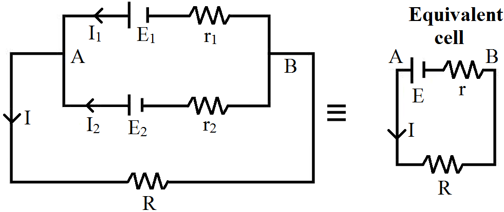
Potential difference across A & B,
$\text{V}=\text{V}_\text{A}-\text{V}_\text{B}=\text{E}_1-\text{I}_1\text{r}_1\ ...(1)$
$\text{V}=\text{V}_\text{A}-\text{V}_\text{B}=\text{E}_2-\text{I}_2\text{r}_2\ ...(2)$
$\Rightarrow\text{I}_1=\frac{\text{E}_1}{\text{r}_1}-\frac{\text{V}}{\text{r}_1}\ ...(3)$ (from (1))
$\text{I}_2=\frac{\text{E}_2}{\text{r}_2}-\frac{\text{V}}{\text{r}_2}\ ...(4)$ (from (2))
For Equivalent cell $\text{I}=\frac{\text{E}}{\text{r}}-\frac{\text{V}}{\text{r}}\ ...(5)$
$\because\text{I}=\text{I}_1+\text{I}_2$
$\therefore\frac{\text{E}}{\text{r}}\frac{\text{V}}{\text{r}}=\Big(\frac{\text{E}_1}{\text{r}_1}-\frac{\text{V}}{\text{r}_1}\Big)+\Big(\frac{\text{E}_2}{\text{r}_2}-\frac{\text{V}}{\text{r}_2}\Big)$
$=\Big(\frac{\text{E}_1}{\text{r}_1}+\frac{\text{E}_2}{\text{r}_2}\Big)-\text{V}\Big(\frac{1}{\text{r}_1}+\frac{1}{\text{r}_2}\Big)$
Comparing we get $\frac{1}{\text{r}}=\frac{1}{\text{r}_1}+\frac{1}{\text{r}_2}$
$\therefore$ Equivalent internal resistance is, $\text{r}=\frac{\text{r}_1\text{r}_2}{\text{r}_1+\text{r}_2}$
Also, $\frac{\text{E}}{\text{r}}=\frac{\text{E}_1}{\text{r}_1}+\frac{\text{E}_2}{\text{r}_2}=\frac{\text{E}_1\text{r}_2+\text{E}_2\text{r}_1}{\text{r}_1\text{r}_2}$
$\therefore$ Equivalent emf is, $\text{E}=\frac{\text{E}_1\text{r}_2+\text{E}_2\text{r}_1}{\text{r}_1+\text{r}_2}$
- $\text{E}=\frac{5\times2+5\times2}{2+2}=5\text{V}$
$\text{r}=\frac{2\times2}{2+2}=1\text{r}$
$\text{I}=\frac{\text{E}}{\text{R}+\text{r}}=\frac{5}{10+1}=\frac{5}{11}\text{A}$
$\therefore$ Voltage across $\text{R}\Rightarrow\text{V}$
$=\text{IR}=\frac{5}{11}\times10=\frac{50}{11}\text{V}=4.54\text{V}$ View full question & answer→Question 523 Marks
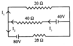
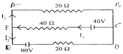
Using Kirchhoff’s rules, calculate the current through the $40\Omega$ and $20\Omega$ resistors in the following circuit: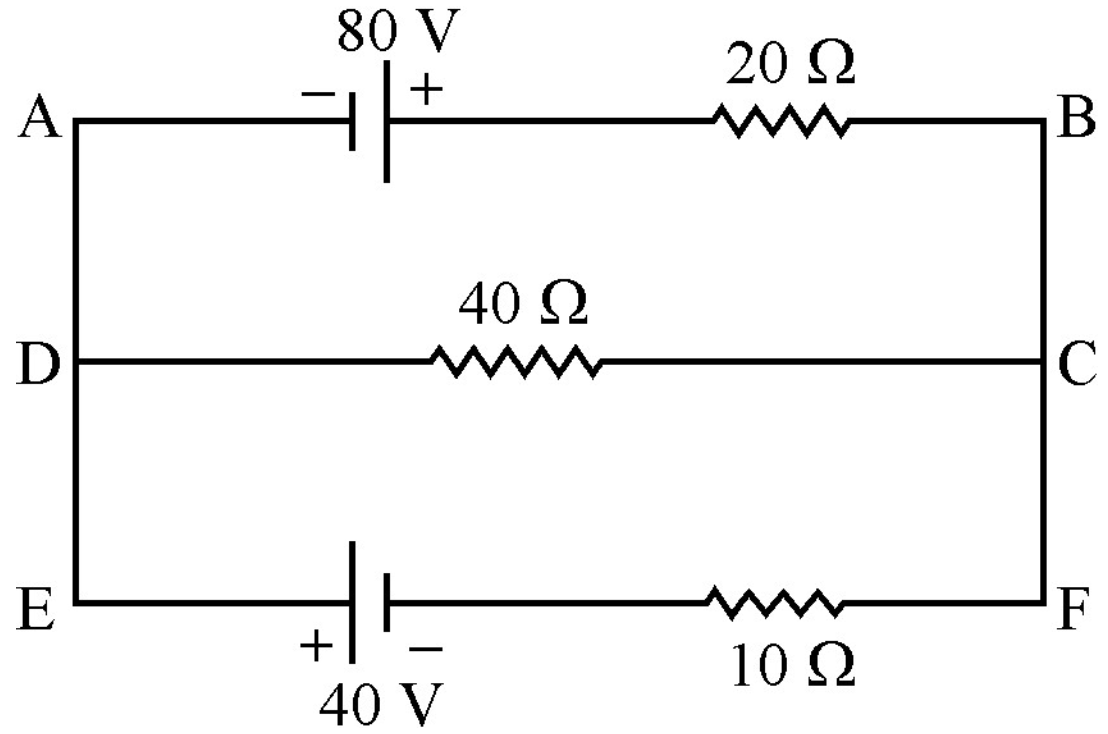
AnswerApply KVL through ABCDA:
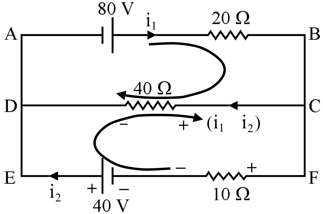
$80 - 20i_1 - 40(i_1 - i_2) = 0 80 - 60i_1 + 40i_2$
= 0 equation (1) Apply KVL through
FEDCF: $40 + 40(i_1 - i_2) - 10i_2$
$= 0 40 + 40i_1 - 50i_2= 0$ equation $= 0 4i_2 - 6i_1 = -8$
equation $(1) -5i_2 + 4i_1 = -4$ equation (2) Multiplying equation (2) by $\frac{6}{4}$ and add with equation (1)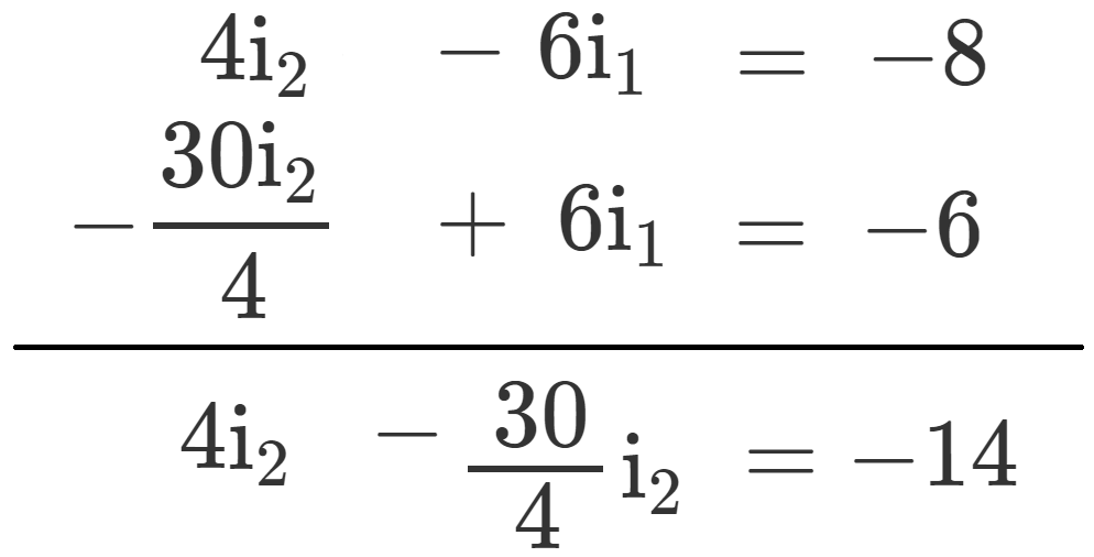
$\frac{-14}{4}\text{i}_2=-14,\text{i}_2=\frac{-14}{7}\times2$ $\text{i}_2=4\text{A}$
Put the value of $i_2$ in equation $(1) 4 \times (4) - 6i_1$
$= -8 16 - 6i_1 = -8 6i_1 = 16 + 8 = 24 i_1 = 4A$
So, current through $40\Omega$ resistor $= i_1 - i_2 = 4 - 4 = 0A$
Current through $20\Omega$ resistor $= 4A$ View full question & answer→Question 533 Marks
What is end error in a metre bridge? How is it overcome? The resistances in the two arms of the metre bridge are $\text{R}=5\Omega$ and S respectively. When the resistance S is shunted with an equal resistance, the new balance length found to be 1.5 $l_1$, where $l_1$ is the initial balancing length. Calculate the value of S.
AnswerThe shifting of zero of the scale at different points as well as the stray resistance gives rise to the end error in meter bridge wire. This error arises due to the non-uniformity of the meter wire End corrections can be estimated by including known resistances $P_1$ and $Q_1$ in the two ends and finding the null point We have
$\text{R}=5\Omega$ According to the wheat stone Bridge principle: $\frac{\text{R}}{\text{l}_1}=\frac{\text{S}}{100-\text{l}_1}$ $\frac{5}{\text{l}_1}=\frac{\text{S}}{100-\text{l}_1}$ equation (1) After shunting means we are connecting resistance in parallel $\text{S}\rightarrow\frac{\text{S}}{2}$ $\frac{5}{1.5\text{l}_1}=\frac{\text{S}}{2(100-1.5\text{l}_1)}$ equation (2) Equation (1) can be written as: $500 - 5l_1= Sl_1$ equation (3) And, equation (2) can be written as $10(100 - 1.5l_1) = 1.5Sl_1$ equation (4) From equation (3) and (4) $\frac{500-5\text{l}_1}{\text{l}_1}=\frac{1000-15\text{l}_1}{1.5\text{l}_1}$ $750-7.5\text{l}_1=1000-15\text{l}_1$ $ -250=-7.5\text{l}_1$ $\text{l}_1=\frac{100}{3}$ $\text{S}=\frac{500-\frac{5\times100}{3}}{\frac{100}{3}}=\frac{500-\frac{500}{3}}{\frac{100}{3}}=\frac{1000}{3}\times\frac{3}{100}$ $\text{S}=10\Omega$ View full question & answer→Question 543 Marks
How many time constants will elapse before the power delivered by a battery drops to half of its maximum value in an RC circuit?
AnswerPower $=\text{CV}^2=\text{Q}\times\text{V}$
Now, $\frac{\text{QV}}{2}=\text{QV}\times\text{e}^{\frac{-\text{t}}{\text{RC}}}$
$\Rightarrow\frac{1}{2}=\text{e}^{\frac{-\text{t}}{\text{RC}}}$
$\Rightarrow\frac{\text{t}}{\text{RC}}=-\text{In}\ 0.5$
$\Rightarrow-(-0.69)=0.69.$
View full question & answer→Question 553 Marks
The following circuit shows the use of potentiometer to measure the internal resistance of a cell:
- When the key is open, how does the balance point change, if the current from the driver cell decreases?
- When the key K is closed, how does the balance point change if R is increased keeping current from the driver cell constant?
Answer
- When current through driver cell decreases, the potential gradient across potentiometer wire decreases; so the balancing length $\text{l}=\frac{\text{E}}{\text{k}}$ increases, so balance point is shifted to the right.
- With increase of R, the terminal p.d. across cell E increases and hence balancing length $\text{l}=\frac{\text{V}}{\text{k}}\propto\text{V}$ increases. So the balance point is shifted to the right.
View full question & answer→Question 563 Marks
Electrons are continuously in motion within a conductor but there is no current in it unless some source of potential is applied across its ends. Give reason.
AnswerIn the absence of any external source the motion of electrons in a conductor is random and electrons collide continuously with the positive ions of metal. This causes a random change in direction of motion. The average velocity of random motion of electrons in any direction is zero, hence current is zero.
View full question & answer→Question 573 Marks
For the potentiometer circuit shown in the given figure, points X and Y represent the two terminals of an unknown emf E'. A student observed that when the jockey is moved from the end A to the end B of the potentiometer wire, the deflection in the galvanometer remains in the same direction.

What may be the two possible faults in the circuit that could result in this observation? If the galvanometer deflection at the end B is (i) more, (ii) less than at the end A, which of the two faults, listed above, would be there in the circuit? Give reason in support of your answer in each case.
AnswerThe two possible faults in the circuit may be (i) emf E′ is greater than emf E.
(ii) Terminal X of unknown emf is negative (while it should be positive).
If galvanometer deflection at end B is more than that at end A, then terminal X is negative, because in this case net current in galvanometer along AB due to both cells is additive.
If galvanometer deflection at end B is less than that at end A, then E′ > E, because net current in galvanometer due to both cells’ emfs E and E′ is subtractive.
View full question & answer→Question 583 Marks
What is the advantage of using thick metallic strips to join wires in a potentiometer?
AnswerMetallic strips have negligible resistance and need not to be counted in the length $l_1,$ of the null point of potentiometer. That's why the thick metallic strips are used in potentiometer. It is for the convenience of experimenter as he measures only their lengths along the straight segments each of lengths 1m.This measurements is done with the help of a centimetre scale or metre scale and leads to the accurate measurements.
View full question & answer→Question 593 Marks
A capacitance C charged to a potential difference V is discharged by connecting its plates through a resistance R. Find the heat dissipated in one time constant after the connections are made. Do this by calculating $\int\text{i}^2\text{R}$ dt and also by finding the decrease in the energy stored in the capacitor.
AnswerEnergy stored at a part time in discharging $=\frac{1}{2}\text{CV}^2\Big(\text{e}^{\frac{-\text{t}}{\text{RC}}}\Big)^2$
Heat dissipated at any time = (Energy stored at t = 0) - (Energy stored at time t)
$=\frac{1}{2}\text{CV}^2-\frac{1}{2}\text{CV}^2\big(-\text{e}^{-1}\big)^2$ $=\frac{1}{2}\text{CV}^2\big(1-\text{e}^2\big)$
View full question & answer→Question 603 Marks
How many time constants will elapse before the current in a charging RC circuit drops to half of its initial value? Answer the same question for a discharging RC circuit.
Answer$\frac{\text{Q}}{2}=\text{Q}\Big(1-\text{e}^{\frac{-\text{t}}{\text{CR}}}\Big)$
$\Rightarrow\frac{1}{2}=\Big(1-\text{e}^{\frac{-\text{t}}{\text{CR}}}\Big)$
$\Rightarrow\text{e}^{\frac{-\text{t}}{\text{CR}}}=\frac{1}{2}$
$\Rightarrow\frac{\text{t}}{\text{RC}}=\log2\Rightarrow\text{n}=0.69.$
View full question & answer→Question 613 Marks
A (i) series (ii) parallel combination of two given resistors is connected, one by one, across a cell. In which case will the terminal potential difference, across the cell have a higher value?
AnswerTerminal potential difference across a cell,
$\text{V}=\varepsilon-\text{lr}$
- In series arrangement, current, $\text{I}_\text{S}=\frac{\text{E}}{\text{R}_1+\text{R}_2+\text{r}}$
- In parallel arrangement, current, $\text{I}_\text{P}=\frac{\text{E}}{\frac{\text{R}_1\text{R}_2}{\text{R}_1+\text{R}_2}+1}$
Obviously, IP > IS, so VP < VS.
That is series arrangement will have higher terminal potential difference. View full question & answer→Question 623 Marks
A capacitor of capacitance $10\mu\text{F}$ is connected across a battery of emf 6.0V through a resistance of $20\text{k}\Omega$ for 4.0s. The battery is then replaced by a thick wire. What will be the charge on the capacitor 4.0s after the battery is disconnected?
Answer$\text{C} = 100\mu\text{F, emf} = 6\text{V}, \text{ R} = 20 \text{K}\Omega, \text{t} = 4 \text{S}.$
Charging: $\text{Q}=\text{CV}\Big(1-\text{e}^{\frac{-\text{t}}{\text{RC}}}\Big)\ \bigg[\frac{-\text{t}}{\text{RC}}=\frac{4}{2\times10^4\times10^{-4}}\bigg]$
$=6\times10^{-4}\big(1-\text{e}^{-2}\big)=5.187\times10^{-4}\text{C}=\text{Q}$
Discharging: $\text{q}=\text{Q}\Big(\text{e}^{\frac{-\text{t}}{\text{RC}}}\Big)=5.184\times10^{-4}\times\text{e}^{-2}$
$=0.7\times10^{-4}\text{C}=70\mu\text{c}.$
View full question & answer→Question 633 Marks
Two heated wires of the same dimensions are first connected in series and then in parallel to a source of supply. What will be the ratio of heat produced in the two cases?
Answer$\text{Q}=\frac{\text{V}^2}{\text{R}}\text{t}\propto\frac{1}{\text{R}}$
For same voltage,
$\frac{\text{Q series}}{\text{Q parallel}}=\frac{\text{R parallel}}{\text{R series}}=\frac{\frac{(\text{R.R})}{\text{(R}+\text{R})}}{\text{R}+\text{R}}=\frac{\frac{\text{R}}{2}}{2\text{R}}=\frac14$
View full question & answer→Question 643 Marks
What length of a copper wire of cross-sectional area $0.01mm^2$ will be needed to prepare a resistance of $1\text{k}\Omega?$ Resistivity of copper $=1.7\times10^{-8}\Omega\text{-m}.$
Answer$\text{f}_\text{cu}=1.7\times10^{-8}\Omega\text{-m}$
$\text{A}=0.01\text{mm}^2=0.01\times10^{-6}\text{m}^2$
$\text{R}=1\text{K}\Omega=10^3\Omega$
$\text{R}=\frac{\text{f}\ell}{\text{a}}$
$\Rightarrow10^3=\frac{1.7\times10^{-8}\times\ell}{10^{-6}}$
$\Rightarrow\ell=\frac{10^3}{1.7}=0.58\times10^3\text{m}=0.6\text{km}.$
View full question & answer→Question 653 Marks
An ideal battery sends a current of 5A in a resistor. When another resistor of value $10\Omega$ is connected in parallel, the current through the battery is increased to 6A. Find the resistance of the first resistor.
Answer$\text{R}_1=\text{R},\text{i}_1=5\text{A}$
$\text{R}_2=\frac{10\text{R}}{10+\text{R}},\text{i}_2=6\text{A}$
Since potential constant,
$\text{i}_1\text{R}_1=\text{i}_2\text{R}_2$
$\Rightarrow5\times\text{R}=\frac{6\times10^\text{R}}{10+\text{R}}$
$\Rightarrow(10+\text{R})5=60$
$\Rightarrow5\text{R}=10\Rightarrow\text{R}=2\Omega.$
View full question & answer→Question 663 Marks
A parallel-plate capacitor with plate area $20cm^2$ and plate separation 1.0mm is connected to a battery. The resistance of the circuit is $10\text{k}\Omega.$ Find the time constant of the circuit.
Answer$\text{A}=20\text{cm}^2=20\times10^{-4}\text{m}^2$
$\text{d}=1\text{mm}=1\times10^{-3}\text{m};\text{R}=10\text{K}\Omega$
$\text{C}=\frac{\text{E}_0\text{A}}{\text{d}}=\frac{8.85\times10^{-12}\times20\times10^{-4}}{1\times10^{-3}}$
$=\frac{8.85\times10^{-12}\times2\times10^{-3}}{10^{-3}}=17.7\times10^{-2}\text{Farad}.$
Time constant $=\text{CR}=17.7\times10^{-2}\times10\times10^3$
$=17.7\times10^{-8}=0.177\times10^{-6}\text{s}=0.18\mu\text{s}.$
View full question & answer→Question 673 Marks
Why are alloys used for making standard resistance coils?
AnswerAlloys are used for making standard resistance coil because they have low temperature coefficient of resistance with less temperature sensitivity.
This keeps the resistance of the wire almost constant even in small temperature change. The alloys also have high resistivity and hence high resistance, because for given length and cross-section area of conductor (L and A are constant).
$\text{R}\hat{\text{I}}\pm\text{p}$ View full question & answer→Question 683 Marks
Calculate the current drawn from the battery in the given network shown here. State Kirchhoff’s loop law and name the law on which it is based.
AnswerThe equivalent circuit is as shown in figure alongside. [$\therefore$ Bridge is in balanced condition, no current flows through $5\Omega$ resistance] $\frac{1}{\text{R}}=\frac{1}{5}+\frac15\text{R}=5\Omega$
Current in the circuit $=\frac{6}{2.5}\text{A}=2.4\text{A}$ Kirchhoff’s Loop Law: The algebraic sum of potential differences of different circuit elements of a closed circuit (or mesh) is zero. This law is based on law of conservation of energy. View full question & answer→Question 693 Marks
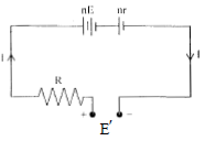
n-identical cells, each of emf $\varepsilon,$ internal resistance r connected in series are charged by a dc source of emf $\varepsilon'$ using a resistance R.
- Draw the circuit arrangement.
- Deduce expressions for (a) the charging current and (b) the potential difference across the combination of cells.
Answer
- The circuit arrangement is shown in figure.
Applying Kirchhoff’s second law to the circuit abcda
$-\text{n}\varepsilon-\text{I}(\text{nr)}-\text{IR}+\varepsilon' = 0$
$\Rightarrow\text{I}=\frac{\varepsilon'-\text{n}\in}{\text{R}+\text{nr}}$
-
- Charging current, $\text{I}=\frac{\in'-\text{n}\varepsilon}{\text{R}+\text{nr}}$
- Potentail difference across the combination V is given by
$-\text{V}-\text{IR}+\text{}\varepsilon'=0$
$\Rightarrow\text{V}=\varepsilon'-\text{IR}$
$\Rightarrow\text{V}=\varepsilon'=\frac{(\varepsilon'-\text{n}\varepsilon)}{\text{R}+\text{nr}}$
$\Rightarrow\text{V}=\frac{\varepsilon'(\text{R}+\text{nr)}-\varepsilon'+\text{n}\varepsilon}{\text{R}+\text{nr}}$
$\Rightarrow\text{V}=\frac{\varepsilon'(\text{R}+\text{nr}-1)+\text{n}\varepsilon}{\text{R}+\text{nr}}$ View full question & answer→Question 703 Marks
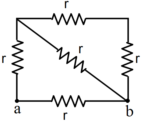
Answer$\text{R}_\text{eff}=\frac{\Big(\frac{2\text{r}}{3}+\text{r}\Big)\text{r}}{\Big(\frac{2\text{r}}{3}+\text{r}+\text{r}\Big)}=\frac{5\text{r}}{8}$ 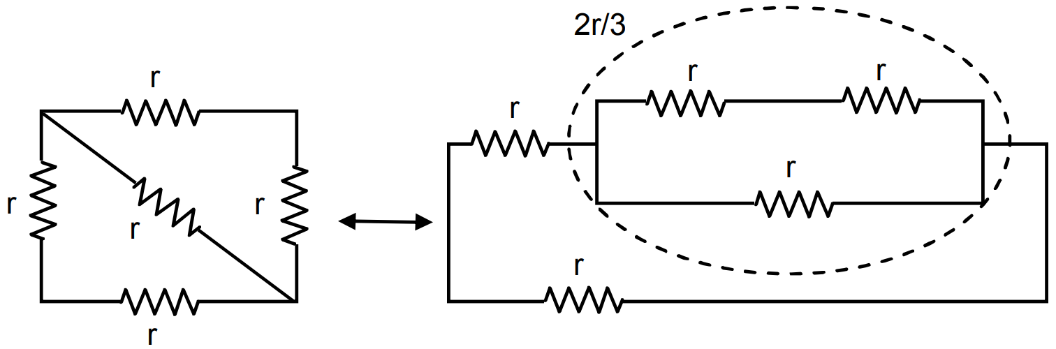 $\text{R}_\text{eff}=\frac{\text{r}}{3}+\text{r}=\frac{4\text{r}}{3}$
  $\text{R}_\text{eff}=\frac{2\text{r}}{2}=\text{r}$
  $\text{R}_\text{eff}=\frac{\text{r}}{4}$
  $\text{R}_\text{eff}=\text{r}$
View full question & answer→Question 713 Marks
Two heater coils made of same material are connected in parallel across the mains. The length and diameter of the wire of one of coils are double that of the other. Which one of them will produce more heat?
AnswerWe have resistance of one wire,
$\text{R}_1=\frac{\rho\text{l}}{\text{A}}=\frac{\rho\text{l}}{\pi\text{r}^2}=\frac{4\rho\text{l}}{\pi\text{D}^2}$
Where l is length and D is diameter of the wire. The resistance of second wire of double the length and double the diameter is,
$\text{R}_2=\frac{4\rho(2\text{l})}{\pi(2\text{D})^2}=\frac{4\rho\text{l}}{\pi\text{D}^2}.\frac12,\text{ i.e.,}\text{ R}_2=\frac{\text{R}_1}{2}$
Heat produced per second,
$\text{H}=\frac{\text{V}^2}{\text{R}}\propto\frac{1}{\text{R}}$
As second coil has resistance equal to half of first coil, therefore heat produced in second coil is double than that in first coil.
View full question & answer→Question 723 Marks
The specification on a heater coil is 250V, 500W. Calculate the resistance of the coil. What will be the resistance of a coil of 1000W to operate at the same voltage?
Answer
- The power consumed by a coil of resistance R when connected across a supply v is $\text{P}=\frac{\text{v}^2}{\text{R}}$
The resistance of the heater coil is, therefore $\text{R}=\frac{\text{v}^2}{\text{P}}=\frac{(250)^2}{500}=125\Omega$
- If, $\text{P}=1000\text{w}$
then, $\text{R}=\frac{\text{v}^2}{\text{P}}=\frac{(250)^2}{1000}=62.5\Omega$ View full question & answer→Question 733 Marks
Name the charge carriers of electric current in:
- Silver foil.
- Hydrogen discharge tube.
- Germanium semiconductor.
- Wire made of alloy nichrome.
- Superconductor.
Answer
- Charge carriers in silver foil are free electrons.
- Charge carriers in hydrogen discharge tube are electrons $(e^–) $ and positive hydrogen ions $(H^+).$
- Charge carriers in germanium semiconductor are electrons $(e^–)$ and holes $(o^+).$
- Charge carriers in nichrome wire are electrons.
- Charge carriers in superconductor are electrons.
View full question & answer→Question 743 Marks
A wire of length 1m and radius 0.1mm has a resistance of $100\Omega.$ Find the resistivity of the material.
Answer$\ell=1\text{m},\text{r}=0.1\text{mm}=0.1\times10^{-3}\text{m}$
$\text{R}=100\Omega,\text{f}=?$
$\Rightarrow\text{R}=\frac{\text{f}\ell}{\text{a}}$
$\Rightarrow\text{f}=\frac{\text{Ra}}{\ell}=\frac{100\times3.14\times0.1\times0.1\times10^{-6}}{1}$
$=3.14\times10^{-6}=\pi\times10^{-6}\Omega\text{-m}.$
View full question & answer→Question 753 Marks
Do all the thermocouples have a neutral temperature?
AnswerAs neutral temperature is The temperature of the hot junction of a thermocouple at which the electromotive force of the thermocouple attains its maximum value, when the cold junction is maintained at a constant temperature of 0°C.
So, answer is yes.
View full question & answer→Question 763 Marks
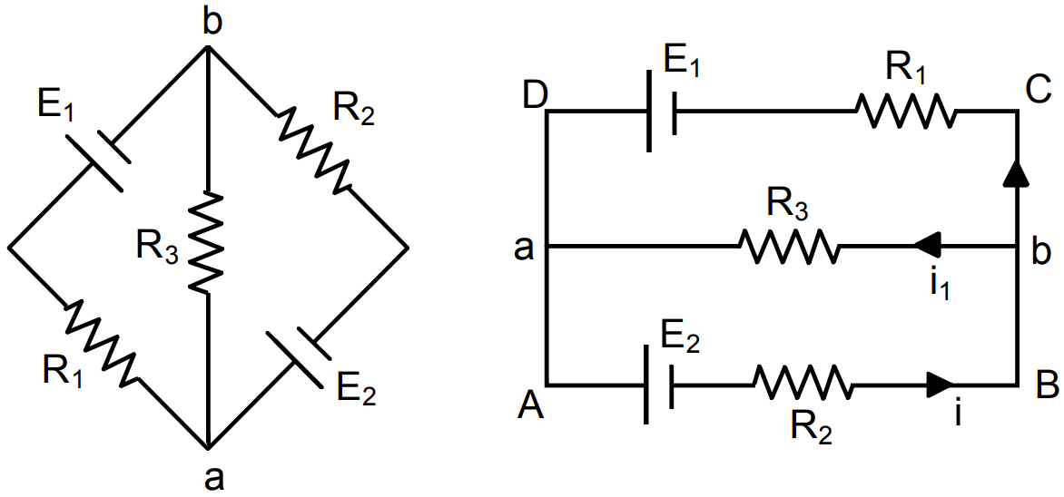
Find the potential difference $V_a - V_b $ in the circuits shown in figure.
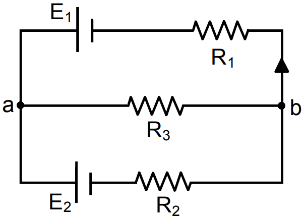
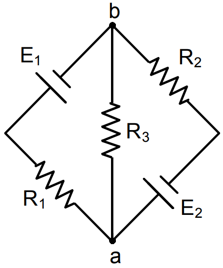
Answer
- In circuit, AB ba A
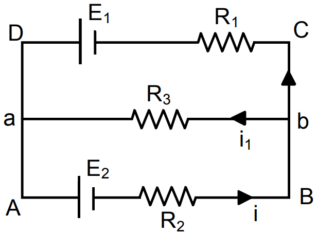
$\text{E}_2+\text{iR}_2+\text{i}_1\text{R}_3=0$
In circuit, $\text{i}_1\text{R}_3+\text{E}_1-(\text{i}-\text{i}_1)\text{R}_1=0$
$\Rightarrow\text{i}_1\text{R}_3+\text{E}_1-\text{iR}_1+\text{i}_1\text{R}_1=0$
$[\text{iR}_2+\text{i}_1\text{R}_3\ \ \ \ \ \ \ \ \ \ \ \ \ \ \ \ \ \ \ \ \ \ =-\text{E}_2]\text{R}_1\\ [\text{iR}_2-\text{i}_1(\text{R}_1+\text{R}_3)\ \ \ \ \ \ \ \ \ =\text{E}_1]\text{R}_2\\\underline{\ \ \ \ \ \ \ \ \ \ \ \ \ \ \ \ \ \ \ \ \ \ \ \ \ \ \ \ \ \ \ \ \ \ \ \ \ \ \ \ \ \ \ \ \ \ \ \ \ \ \ \ \ \ \ \ \ }\\\text{iR}_2\text{R}_1+\text{i}_1\text{R}_3\text{R}_1\ \ \ \ \ \ \ \ \ \ \ \ \ =-\text{E}_2\text{R}_1\\\text{iR}_2\text{R}_1-\text{i}_1\text{R}_2(\text{R}_1+\text{R}_3)=\ \ \ \text{E}_1\text{R}_2\\\underline{ \ \ \ \ \ \ \ \ \ \ \ \ \ \ \ \ \ \ \ \ \ \ \ \ \ \ \ \ \ \ \ \ \ \ \ \ \ \ \ \ \ \ \ \ \ \ \ \ \ \ \ \ \ \ \ \ \ }$
$\text{iR}_3\text{R}_1+\text{i}_1\text{R}_2\text{R}_1+\text{i}_1\text{R}_2\text{R}_3=\text{E}_1\text{R}_2-\text{E}_1\text{R}_1$
$\Rightarrow\text{i}_1(\text{R}_3\text{R}_1+\text{R}_2\text{R}_1+\text{R}_2\text{R}_3)=\text{E}_1\text{R}_2-\text{E}_2\text{R}_1$
$\Rightarrow\text{i}_1=\frac{\text{E}_1\text{R}_2-\text{E}_2\text{R}_1}{\text{R}_3\text{R}_1+\text{R}_2\text{R}_1+\text{R}_2\text{R}_3}$
$\Rightarrow\frac{\text{E}_1\text{R}_2\text{R}_3-\text{E}_2\text{R}_1\text{R}_3}{\text{R}_3\text{R}_1+\text{R}_2\text{R}_1+\text{R}_2\text{R}_3}=\Bigg(\frac{\frac{\text{E}_1}{\text{R}_1}-\frac{\text{E}_2}{\text{R}_2}}{\frac{1}{\text{R}_2}+\frac{1}{\text{R}_1}+\frac{1}{\text{R}_3}}\Bigg)$
- $\therefore$ Same as a
View full question & answer→Question 773 Marks
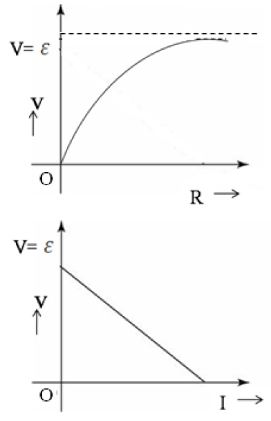
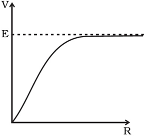
A cell of emf E and internal resistance r is connected across an external resistance R. Plot a graph showing the variation of P.D. across R, verses R.
AnswerWhen the cell of emf E and internal resistance r is connected across an external resistance R, the relationship between the voltage across R is given by
$\text{V}=\frac{\text{E}}{\big[1+\big(\frac{\text{r}}{\text{R}}\big)\big]}$
From the above relation,
Now, as $\text{R}=0\Rightarrow\ \text{V}=0\ \&\ \text{R}=\infty\Rightarrow\ \text{V}=\text{E}.$ So, this variation is shown in the figure given below.
View full question & answer→Question 783 Marks
Two electric bulbs have the following specifications.
- 100W at 220V.
- 1000W at 220V.
Which bulb has higher resistance? What is the ratio of their resistances?
AnswerThe resistance of filament,
$\text{R}=\frac{\text{V}}{\text{I}}=\frac{\text{V}^2}{\text{P}}$
At constant voltage V, the resistance,
$\text{R}\propto\frac{1}{\text{p}}$
That is the resistance of filament of 100W bulb is greater than that of 1000W bulb.
The ratio of resistances $=\frac{\text{R}_1}{\text{R}_2}=\frac{\text{P}_2}{\text{P}_1}$
$=\frac{1000}{100} $
$=\frac{10}{1}=10:1$
View full question & answer→Question 793 Marks
The graph shown here shows the variation of terminal potential difference V, across a combination of three cells in series to a resistor, versus current i:
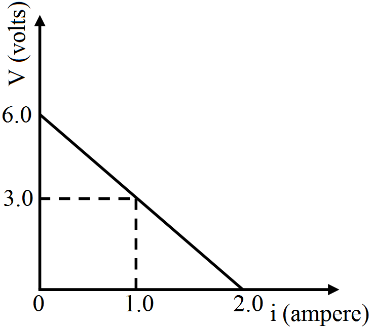
- Calculate the emf of each cell.
- For what current i, will the power dissipation of the circuit be maximum?
AnswerLet $\varepsilon$ be emf and r the internal resistance of each cell. The equation of terminal potential difference.
V = $\varepsilon$ eff - i rint becomes,
V = $3\varepsilon$ -i rint …(i)
Where rint is effective (total) internal resistance.
From fig., when i = 0, V = 6.0V
$\therefore$ From (i), $6=3\varepsilon-0\Rightarrow\varepsilon=\frac63=2\text{V}$
i.e., emf of each cell, $\varepsilon=2\text{V}$
Thus, emf of each cell, $\varepsilon=\text{2V}.$
View full question & answer→Question 803 Marks
AB is a potentiometer wire (Fig). If the value of R is increased, in which direction will the balance point J shift?
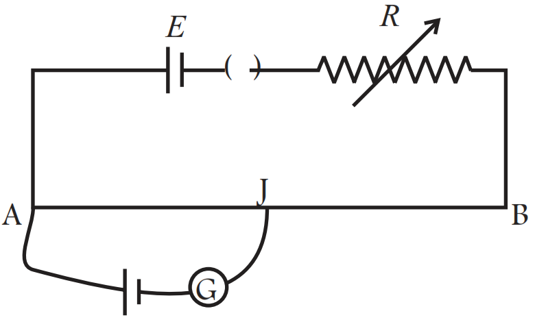
AnswerIf the value of R is increased, the current through the wire will decrease which in turn decreases the potential difference across AB, and hence potential gradient (k) across AB decreases.
Since, at neutral point, for given emf of cell, l increases as potential gradient (k) across AB has decreased because E' = kI
Thus, with the increase of l, which will result in increase in balance length. So, jockey J will shift towards B.
View full question & answer→Question 813 Marks
An electric bulb, when connected across a power supply of 220V, consumes a power of 60W. If the supply drops to 180V, what will be the power consumed? If the supply is suddenly increased to 240V, what will be the power consumed?
Answer$\text{E}=220\text{v}$
$\text{P}=60\text{w}$
$\text{R}=\frac{\text{V}^2}{\text{P}}=\frac{220\times220}{60}$
$=\frac{220\times11}{3}\Omega$
- $\text{E}=180\text{v}$
$\text{P}=\frac{\text{V}^2}{\text{R}}$
$=\frac{180\times180\times3}{220\times11}=40.16\approx40\text{w}$
- $\text{E}=240\text{v}$
$\text{P}=\frac{\text{V}^2}{\text{R}}$
$=\frac{240\times240\times3}{220\times11}=71.4\approx71\text{w}$ View full question & answer→Question 823 Marks
Calculate the temperature at which the resistance of a conductor becomes 20% more than its resistance at 27°C. The value of the temperature coefficient of resistance of the conductor is $2.0 \times 10\frac{-4}{\text{K}}.$
AnswerGiven, $\text{R}_{27}=\text{R}(\text{say}),\text{R}_\text{T}=\text{R}+\frac{20}{100}\text{R}=1.2\text{R},\text{T}_1=27+273=300\text{K}$
From relation,
$\text{R}\text{T}=\text{R}_{27}[1+\alpha(\text{T}_2-300)]$
$\Rightarrow1.2\text{R}=\text{R}[1+2.0\times10^{-4}(\text{T}_2-300)]$
$\Rightarrow1+2.0\times10^{-4}(\text{T}_2-300)=1.2$
$\Rightarrow2.0\times10^{-4}(\text{T}_2-300)=0.2$
$\text{T}_2-300=\frac{0.2}{2.0\times10^{-4}}$
$\text{T}_2=1000+300=1300\text{K}$
View full question & answer→Question 833 Marks
Two wires A and B of the same material and having same length, have their cross sectional areas in the ratio 1 : 6. What would be the ratio of heat produced in these wires when same voltage is applied across each?
Answer$\text{A}_\text{A}:\text{A}_\text{B}=1:6$
$\text{H}-\text{V}^2\frac{\text{t}}{\text{R}}$ and $\text{R}=\frac{\rho\text{l}}{\text{A}}$
$\text{H}_\text{A}=\frac{\text{V}^2\text{t}}{\frac{\rho\text{l}}{\text{A}_\text{A}}};\text{H}_\text{B}=\frac{\text{V}^2\text{t}}{\frac{\rho\text{l}}{\text{A}_\text{B}}}$
$=\frac{\text{H}_\text{A}}{\text{H}_\text{B}}=\frac{\text{V}^2\text{t}\times\text{A}_\text{A}}{\rho\text{l}}\times\frac{\rho\text{l}}{\text{V}^2\text{tA}_\text{H}}$
$\Rightarrow\frac{\text{H}_\text{A}}{\text{H}_\text{B}}=\frac{\text{A}_\text{A}}{\text{A}_\text{B}}=1:6$
View full question & answer→Question 843 Marks
You are given n resistors each of resistance r. They are first connected to get the minimum possible resistance. In the second case, these are again connected differently to get the maximum possible resistance. Calculate the ratio between minimum and maximum values of resistance so obtained.
AnswerFor minimum possible resistance, the resistors should be connected in parallel
$\frac{1}{\text{r}_\text{p}}=\frac{1}{\text{r}}+\frac{1}{\text{r}}+\dots\text{n}\text{ times}$
$\frac{1}{\text{r}_\text{p}}=\frac{\text{n}}{\text{r}}$
$\text{r}_\text{p}=\frac{\text{r}}{\text{n}}$
For maximum possible resistance, the resistors should be connected in series,
$\text{r}_\text{s}=\text{r}+\text{r}+\dots\text{n times}$
$\text{r}_\text{s}=\text{nr}$
$\text{Ratio}\frac{\text{r}_\text{p}}{\text{r}_\text{s}}=\frac{\text{r}}{\text{n}}\times\frac{1}{\text{nr}}=\frac{1}{\text{n}^2}$
View full question & answer→Question 853 Marks
A heater coil is cut in two parts and only one of them is used in the heater. What is the ratio of the heat produced by this half coil to that by the original coil if the voltage applied is the same?
AnswerFor same p.d. the heat produced per second,
$\text{H}=\frac{\text{V}^2}{\text{R}}\propto\frac{1}{\text{R}}.$
As the one part of heater coil has resistance $\text{R}_2=\frac{\text{R}}{2}$ being the resistance of original coil; therefore the ratio of heat produced,
$\frac{\text{H}_2}{\text{H}_1}=\frac{\text{R}_1}{\text{R}_2}=\frac{\text{R}}{\frac{\text{R}}{2}}=2:1$
View full question & answer→Question 863 Marks
The current through a wire depends on time as $\text{i}=\text{i}_0+\alpha\text{t},$
Where $\text{i}_0=10\text{A}$ and $\alpha=4\text{A/ s}.$ Find the charge that crosses through a section of the wire in 10 seconds.
Answer$\text{i}=\text{i}_0+\alpha\text{t},\ \text{t}=10\text{sec},$ $\text{i}_0=10\text{A},\alpha=4\text{A}/\text{ sec}$
$\text{q}=\int\limits^\text{t}_0\text{idt}=\int\limits^\text{t}_0(\text{i}_0+\alpha\text{t})\text{dt}=\int\limits^\text{t}_0\text{i}_0\text{dt}+\int\limits^\text{t}_0\alpha\text{tdt}$
$=\text{i}_0\text{t}+\alpha\frac{\text{t}^2}{2}=10\times10+4\times\frac{10\times10}{2}$
$=100+200=300\text{C}.$
View full question & answer→Question 873 Marks
A voltage of 30V is applied across a carbon resistor with first, second and third rings of blue, black and yellow colours respectively. Calculate the value of current in mA, through the resistor.
AnswerValue of first digit (blue ring) = 6
Value of second digit (black ring) = 0
Multiplier (yellow ring) = 104
$\therefore$ Resistance, $\text{R} = 60 \times104\Omega, $ Voltage, V = 30V
Current $\text{I}=\frac{\text{V}}{\text{R}}=\frac{30}{60\times10^4}=0.5\times10^{-4}\text{A}=0.05\text{mA.}$
View full question & answer→Question 883 Marks
Is the motion of a charge across junction momentum conserving? Why or why not?
AnswerIn the circuit when an electron approaches a junction, in addition to the uniform E that faces it normally (which keep the drift velocity fixed), as drift velocity $(v_d)$ is directly proportional to Electric field (E). That’s why there are accumulation of charges on the surface of wires at the junction.
These produce additional electric fields. These fields alter the direction of momentum. Thus, the motion of a charge across junction is not momentum conserving.
View full question & answer→Question 893 Marks
What are the advantages of the null-point method in a Wheatstone bridge? What additional measurements would be required to calculate $R_{unknown}$ by any other method?
AnswerThe advantage of null point method in a Wheatstone bridge is that the resistance of galvanometer does not affect the balance point and there is no need to determine current in resistances and galvanometer and the internal resistance of ab galvanometer.
$R_{unknown}$ can be calculated applying Kirchhoff’s rules to the circuit.
We would need additional accurate measurement of all the currents in resistances and galvanometer and internal resistance of the galvanometer.
View full question & answer→Question 903 Marks
A resistance $\text{R}=4\Omega$ is connected to one of the gaps in a meter bridge, which uses a wire of length 1m. An unknown resistance $\text{x}>4\Omega$ is connected in the other gap as shown in the figure. The balance point is noticed at ‘l’ cm from the positive end of the battery. On interchanging R and X, it is found that the balance point further shifts by 20cm (away from the end A). Neglecting the end correction calculate the value of unknown resistance ‘X’ used.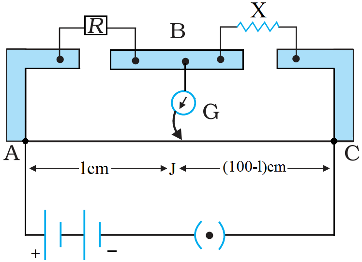
AnswerFrom 'meter bridge' formula,
$\frac{\text{R}}{\text{X}}=\frac{\text{l}}{100-\text{l}}$
$\Rightarrow\text{X}=\frac{100-\text{l}}{\text{l}}\text{R}$
Given, $\text{R}=4\Omega$
$\therefore\text{X}=\frac{(100-\text{l})}{\text{l}}\times4\Omega\ \dots\text{(i)}$
On interchanging R and X, the balance point is obtained at a distance (l + 20)cm from end A, so
$\frac{\text{X}}{\text{R}}=\frac{\text{l}+20}{100-(\text{l}+20)}$
$\Rightarrow\text{X}=\frac{\text{l}+20}{80-\text{l}}\times4\Omega\ \dots\text{(ii)}$
Equating (i) and (ii)
$\frac{(100-\text{l})}{\text{l}}\times4=\frac{\text{l}+20}{80-\text{l}}\times4$
Solving we get l = 40cm
$\therefore$ Unknown resistance, $\text{X}=\frac{100-\text{l}}{\text{l}}\times\text{4}\Omega=\frac{100-40}{40}\times4\Omega$
$\Rightarrow\text{X}=6\Omega$
View full question & answer→Question 913 Marks
How many time constants will elapse before the charge on a capacitors falls to 0.1% of its maximum value in a discharging RC circuit?
Answer$\text{q}=\text{Qe}^{\frac{-\text{t}}{\text{RC}}}$
$\text{q}=0.1\%\text{ Q}$
$\text{RC}\Rightarrow\text{Time constant}$
$=1\times10^{-3}\text{Q}$
So, $1\times10^{-3}\text{Q}=\text{Q}\times\text{e}^{\frac{-\text{t}}{\text{RC}}}$
$\Rightarrow\text{e}^{\frac{-\text{t}}{\text{RC}}}=\text{In}\ 10^{-3}$
$\Rightarrow\frac{\text{t}}{\text{RC}}=-(-6.9)=6.9$
View full question & answer→Question 923 Marks
A plate of area $10cm^2$ is to be electroplated with copper (density $9000kg/m^3$) to a thickness of 10 micrometres on both sides, using a cell of 12V. Calculate the energy spent by the cell in the process of deposition. If this energy is used to heat 100g of water, calculate the rise in the temperature of the water. ECE of copper $= 3 \times 10^{-7}kg C^{-1}$ and specific heat capacity of water $= 4200Jkg^{-1}.$
AnswerSurface area of the plate, $A=10 \mathrm{~cm}^2=10 \times 10^{-4} \mathrm{~m}^2$
Thickness of copper deposited, $\mathrm{t}=10 \mu \mathrm{~m}=10^{-5} \mathrm{~m}$
Density of copper $=9000 \mathrm{~kg} / \mathrm{m}^3$
Volume of copper deposited, $\mathrm{V}=\mathrm{A}(2 \mathrm{t}) \mathrm{V}=10 \times 10^{-4} \times 2 \times 10 \times 10^{-6}$
$=2 \times 10^2 \times 10^{-10}$
$=2 \times10^{-8} \mathrm{~m}^3$ Mass of copper deposited, $\mathrm{m}=$ Volume $\times$
Density $=2 \times 10^{-8} \times 9000$
$ \Rightarrow \mathrm{~m}=18 \times 10^{-5} \mathrm{~kg}$
Using the formula, $\mathrm{m}=\mathrm{ZQ}$,
We get, $18 \times 10^{-5} \mathrm{~kg}=3 \times 10^{-7} \times \mathrm{Q} $
$\Rightarrow \mathrm{Q}=6 \times 10^2 \mathrm{C}$
Energy spent by the cell $=$ Work done by the cell
$ \Rightarrow W=V Q $
$ =2 \times 6 \times 10^2 $
$=72 \times 10^2=7.2 \mathrm{~kJ}$
Let $\Delta\theta$ be the rise in temperature of water. When this energy is used to heat 100g of water,
We have,
$72 \times 10^3$
$= 100 × 10^{-3 }\times4200\times\Delta\theta$
$\Rightarrow\Delta\theta=17\text{K}$
View full question & answer→Question 933 Marks
A cylindrical metallic wire is stretched to increase its length by 10%. Calculate the percentage increase in its resistance.
AnswerWhen the same wire is stretched, it's length increases but cross-sectional area decreases. The change in resistance is due to both increase in length and decrease in cross-sectional area.
Valume V = lA = Costans, $\text{A}=\frac{\text{V}}{\text{l}}=$ constant
$\therefore\text{R}=\frac{\rho\text{l}}{\text{A}}=\frac{\rho\text{l}^2}{\text{V}}\propto\text{l}^2$
$\therefore\frac{\text{R}'}{\text{R}}=\Big(\frac{\text{l}'}{\text{l}}\Big)^2$
Given, $\text{l}'=\text{l}+\frac{10}{100}\text{l}=1.1\text{l}$
$\Rightarrow\frac{\text{l}'}{\text{l}}=1.1$
$\frac{\text{R}'}{\text{R}}=(1.1)^2=1.21$
% increase in resistance,
$\frac{\text{R}'-\text{R}}{\text{R}}\times100\%=\Big(\frac{\text{R}'}{\text{R}}-1\Big)\times100\%=(1.21-1\times100\%=21\%$
View full question & answer→Question 943 Marks
The potential difference between the terminals of a battery of emf 6.0V and internal resistance $1\Omega$ drops to 5.8V when connected across an external resistor. Find the resistance of the external resistor.
Answer$\text{E}=6\text{V},\text{r}=1\Omega,\text{V}=5.8\text{V},\text{R}=?$
$\text{l}=\frac{\text{E}}{\text{R}+\text{r}}=\frac{6}{\text{R}+1},\text{V}=\text{E}-\text{lr}$
$\Rightarrow5.8=6-\frac{6}{\text{R}+1}\times1\Rightarrow\frac{6}{\text{R}+1}=0.2$
$\Rightarrow\text{R}+1=30\Rightarrow\text{R}=29\Omega.$
View full question & answer→Question 953 Marks
The potential difference across a resistor ‘r’ carrying current ‘I’ is Ir.
- Now if the potential difference across ‘r’ is measured using a voltmeter of resistance ‘RV’, show that the reading of voltmeter is less than the true value
- Find the percentage error in measuring the potential difference by a voltmeter.
- At what value of RV, does the voltmeter measures the true potential difference?
Answer
- V = lr (without voltmeter $R_V$)
$\text{V}'=\frac{\text{lrR}_\text{V}}{\text{r}+\text{R}_\text{V}}=\frac{\text{Ir}}{1+\frac{\text{r}}{\text{R}_\text{V}}}$
$\text{V}'<\text{V}$
- Percentage error,
$\Big(\frac{\text{V}-\text{V}'}{\text{V}}\Big)\times100=\Big(\frac{\text{r}}{\text{r}+\text{R}_\text{V}}\Big)\times100$
- $\text{R}_\text{V}\xrightarrow{\ \ \ \ \ \ }\infty,\text{V}'=\text{lr}=\text{V}$
View full question & answer→Question 963 Marks
A uniform wire of resistance $100\Omega$ is melted and recast as a wire of length is double that of the original. What would be the resistance of the wire?
Answer$\ell'=2\ell$
Volume of the wire remains constant.
$\text{A}\ell=\text{A}'\ell'$
$\Rightarrow\text{A}\ell=\text{A}'\times2\ell$
$\Rightarrow\text{A}'=\frac{\text{A}}{2}$
f = Specific resistance
$\text{R}=\frac{\text{f}\ell}{\text{A}};\text{R}'=\frac{\text{f}\ell'}{\text{A}'}$
$100\Omega=\frac{\text{f}2\ell}{\text{A}/2}=\frac{4\text{f}\ell}{\text{A}}=4\text{R}$
$\Rightarrow4\times100\Omega=400\Omega$
View full question & answer→Question 973 Marks
Two primary cells of emfs wire $\varepsilon_1$ and $\varepsilon_2(\varepsilon_1>\varepsilon_2)$ are connected to a potentiometer wire AB as shown in fig. If the balancing lengths for the two combinations of the cells are 250cm and 400cm, find the ratio of $\varepsilon_1$ and $\varepsilon_2.$
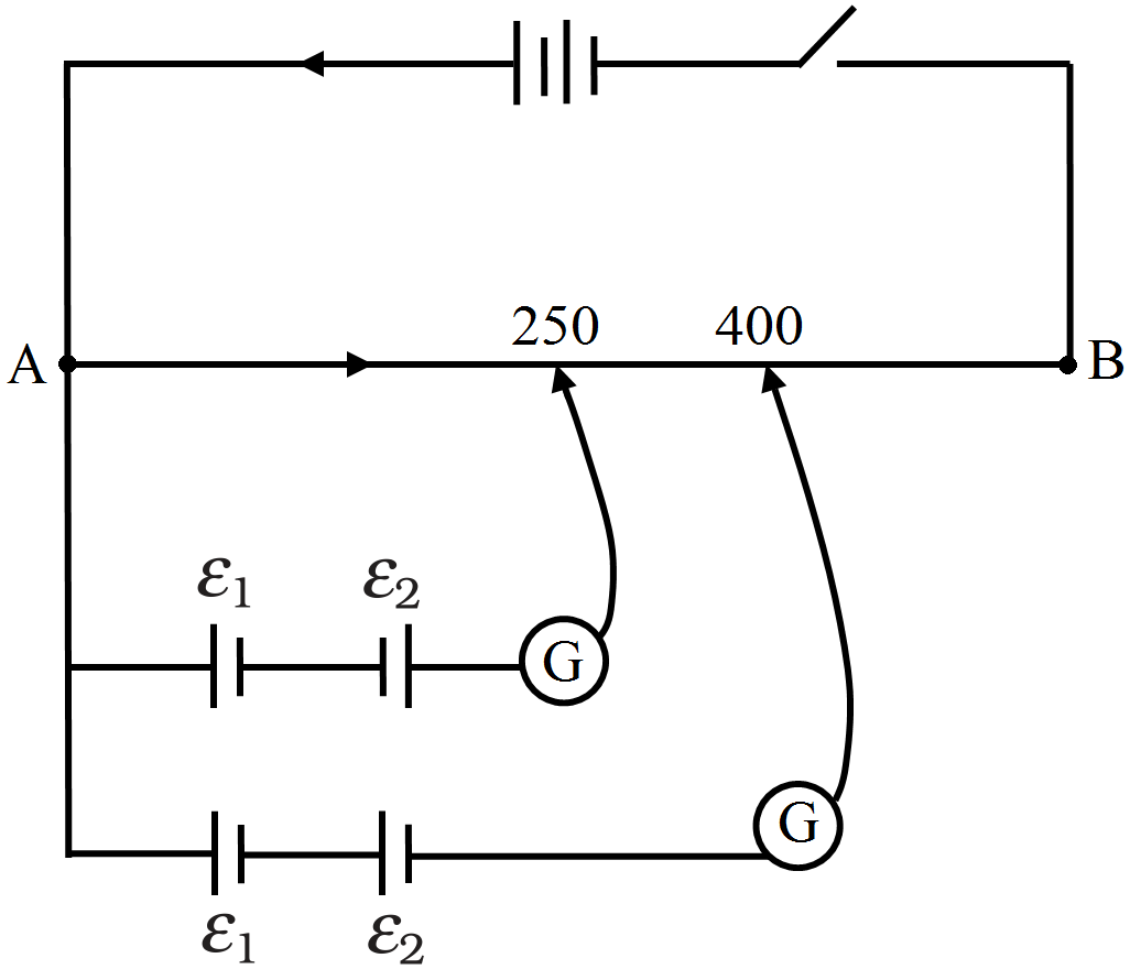
AnswerIn first combination $\varepsilon_1$ and $\varepsilon_2$ are opposing each other while in second combination $\varepsilon_1$ and $\varepsilon_2$ are adding each other,
So,
$\varepsilon_1-\varepsilon_2=\text{Kl}_1$
$\varepsilon_1+\varepsilon_2=\text{kl}_2$
$\frac{\varepsilon_1-\varepsilon_2}{\varepsilon_1+\varepsilon_2}=\frac{\text{l}_1}{\text{l}_1}$
$\Rightarrow\frac{\varepsilon_1-\varepsilon_2}{\varepsilon_1+\varepsilon_2}=\frac{250}{400}$
$\Rightarrow\frac{\varepsilon_1-\varepsilon_2}{\varepsilon_1+\varepsilon_2}=\frac{5}{8}$
$\Rightarrow8\varepsilon_1-8\varepsilon_2=5\varepsilon_1+5\varepsilon_2$
$\Rightarrow3\varepsilon_1=13\varepsilon_2$
$\therefore\frac{\varepsilon_1}{\varepsilon_2}=\frac{13}{3}$
$\therefore\varepsilon_1:\varepsilon_2=13:32$
View full question & answer→Question 983 Marks
A coil of resistance $100\Omega$ is connected across a battery of emf 6.0V. Assume that the heat developed in the coil is used to raise its temperature. If the heat capacity of the coil is 4.0J/K, how long will it take to raise the temperature of the coil by 15^^\circC?
Answer$\text{R}=100\Omega,$
$\text{E}=6\text{v}$
Heat capacity of the coil $=4\text{J/k}$
$\Delta\text{T}=15^\circ$
Heat liberate $\Rightarrow\frac{\text{E}^2}{\text{Rt}}=4\text{J/K}\times15$
$\Rightarrow\frac{6\times6}{100}\times\text{t}=60$
$\Rightarrow\text{t}=166.67\text{sec}=2.8\text{min}$
View full question & answer→Question 993 Marks
The four arms of a Wheatstone bridge $($Fig. $3.19)$ have the following resistances:
$AB =100 \Omega, BC =10 \Omega, CD =5 \Omega \text {, and } DA =60 \Omega \text {. }$
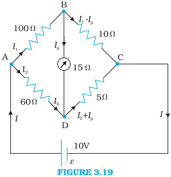
A galvanometer of $15 \Omega$ resistance is connected across $BD$.
Calculate the current through the galvanometer when a potential difference of $10 V$ is maintained across $AC$. AnswerConsidering the mesh $\text{BADB},$ we have
$100 I_1+15 I_g-60 I_2=0$
$\text { or } 20 I_1+3 I_g-12 I_2=0\quad\quad\quad \text{[3.65(a)]}$
Considering the mesh $\text{BCDB}$, we have
$10\left(I_1-I_g\right)-15 I_g-5\left(I_2+I_g\right)=0$
$10 I_1-30 I_g-5 I_2=0$
$2 I_1-6 I_g-I_2=0 \quad\quad\quad\text{[3.65(b)]}$
Considering the mesh $\text{ADCEA},$
$60 I_2+5\left(I_2+I_g\right)=10$
$65 I_2+5 I_g=10$
$13 I_2+I_g=2 \quad\quad\quad\text{[3.65(c)]}$
Multiplying Eq. $(3.65b)$
by $10 \ \ 20 I_1-60 I_g-10 I_2=0 \quad\quad\quad\text{[3.65(d)]}$
From Eqs. $(3.65d)$ and $(3.65a)$ we have
$63 I_g-2 I_2=0$
$I_2=31.5 I_g \quad\quad\quad\text{[3.65(e)]}$
Substituting the value of $I_2$ into Eq. $[3.65(c)]$, we get
$13\left(31.5 I_g\right)+I_g=2$
$410.5 I_g=2$
$I_g=4.87 mA .$
View full question & answer→Question 1003 Marks
A battery of $10 V$ and negligible internal resistance is connected across the diagonally opposite corners of a cubical network consisting of 12 resistors each of resistance $1 \Omega$ (Fig. 3.16). Determine the equivalent resistance of the network and the current along each edge of the cube.
AnswerThe network is not reducible to a simple series and parallel combinations of resistors. There is, however, a clear symmetry in the problem which we can exploit to obtain the equivalent resistance of the network.
The paths $AA ^{\prime}, AD$ and $AB$ are obviously symmetrically placed in the network. Thus, the current in each must be the same, say, $I$. Further, at the corners $A ^{\prime}, B$ and $D$, the incoming current $I$ must split equally into the two outgoing branches. In this manner, the current in all the 12 edges of the cube are easily written down in terms of $I$, using Kirchhoff's first rule and the symmetry in the problem.
Next take a closed loop, say, ABCC'EA, and apply Kirchhoff's second rule:
$
-I R-(1 / 2) I R-I R+\varepsilon=0
$
where $R$ is the resistance of each edge and $\varepsilon$ the emf of battery. Thus,
$
\varepsilon=\frac{5}{2} I R
$
The equivalent resistance $R_{e q}$ of the network is
$
R_{e q}=\frac{\varepsilon}{3 I}=\frac{5}{6} R
$
For $R=1 \Omega, R_{e q}=(5 / 6) \Omega$ and for $\varepsilon=10 V$, the total current ( $=3 I$ ) in the network is
$
3 I=10 V /(5 / 6) \Omega=12 \text { A, i.e., } I=4 A
$
The current flowing in each edge can now be read off from the Fig. 3.16.
View full question & answer→Question 1013 Marks
An electric toaster uses nichrome for its heating element. When a negligibly small current passes through it, its resistance at room temperature $\left(27.0^{\circ} C \right)$ is found to be $75.3 \Omega$. When the toaster is connected to a $230 V$ supply, the current settles, after a few seconds, to a steady value of $2.68 A$. What is the steady temperature of the nichrome element? The temperature coefficient of resistance of nichrome averaged over the temperature range involved, is $1.70 \times 10^{-4}{ }^{\circ} C ^{-1}$.
AnswerWhen the current through the element is very small, heating effects can be ignored and the temperature $T_1$ of the element is the same as room temperature. When the toaster is connected to the supply, its initial current will be slightly higher than its steady value of $2.68 A$. But due to heating effect of the current, the temperature will rise. This will cause an increase in resistance and a slight decrease in current. In a few seconds, a steady state will be reached when temperature will rise no further, and both the resistance of the element and the current drawn will achieve steady values. The resistance $R_2$ at the steady temperature $T_2$ is
$
R_2=\frac{230 V }{2.68 A }=85.8 \Omega
$
Using the relation
$
R_2=R_1\left[1+\alpha\left(T_2-T_1\right)\right]
$
with $\alpha=1.70 \times 10^{-4}{ }^{\circ} C ^{-1}$, we get
$
T_2-T_1=\frac{(85.8-75.3)}{(75.3) \times 1.70 \times 10^{-4}}=820^{\circ} C
$
that is, $T_2=(820+27.0){ }^{\circ} C =847{ }^{\circ} C$
Thus, the steady temperature of the heating element (when heating effect due to the current equals heat loss to the surroundings) is $847^{\circ} C$.
View full question & answer→Question 1023 Marks
(a) In Example 3.1, the electron drift speed is estimated to be only a few $mm s ^{-1}$ for currents in the range of a few amperes? How then is current established almost the instant a circuit is closed?
(b) The electron drift arises due to the force experienced by electrons in the electric field inside the conductor. But force should cause acceleration. Why then do the electrons acquire a steady average drift speed?
(c) If the electron drift speed is so small, and the electron's charge is small, how can we still obtain large amounts of current in a conductor?
(d) When electrons drift in a metal from lower to higher potential, does it mean that all the 'free' electrons of the metal are moving in the same direction?
(e) Are the paths of electrons straight lines between successive collisions (with the positive ions of the metal) in the (i) absence of electric field, (ii) presence of electric field?
Answer(a) Electric field is established throughout the circuit, almost instantly (with the speed of light) causing at every point a local electron drift. Establishment of a current does not have to wait for electrons from one end of the conductor travelling to the other end. However, it does take a little while for the current to reach its steady value.
(b) Each 'free' electron does accelerate, increasing its drift speed until it collides with a positive ion of the metal. It loses its drift speed after collision but starts to accelerate and increases its drift speed again only to suffer a collision again and so on. On the average, therefore, electrons acquire only a drift speed.
(c) Simple, because the electron number density is enormous, $\sim 10^{29} m ^{-3}$.
(d) By no means. The drift velocity is superposed over the large random velocities of electrons.
(e) In the absence of electric field, the paths are straight lines; in the presence of electric field, the paths are, in general, curved.
View full question & answer→