Question 15 Marks
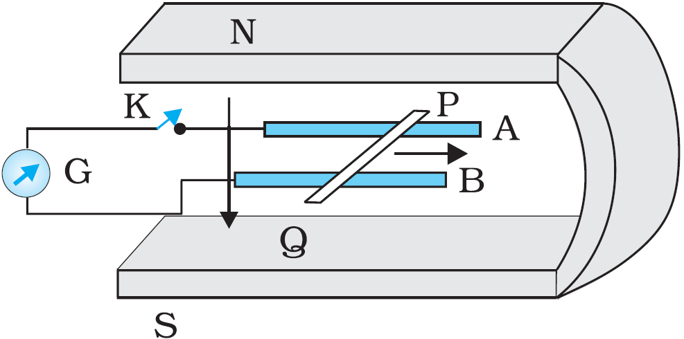
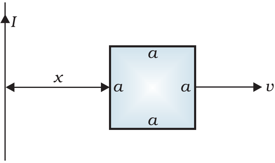
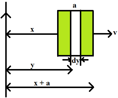
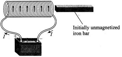
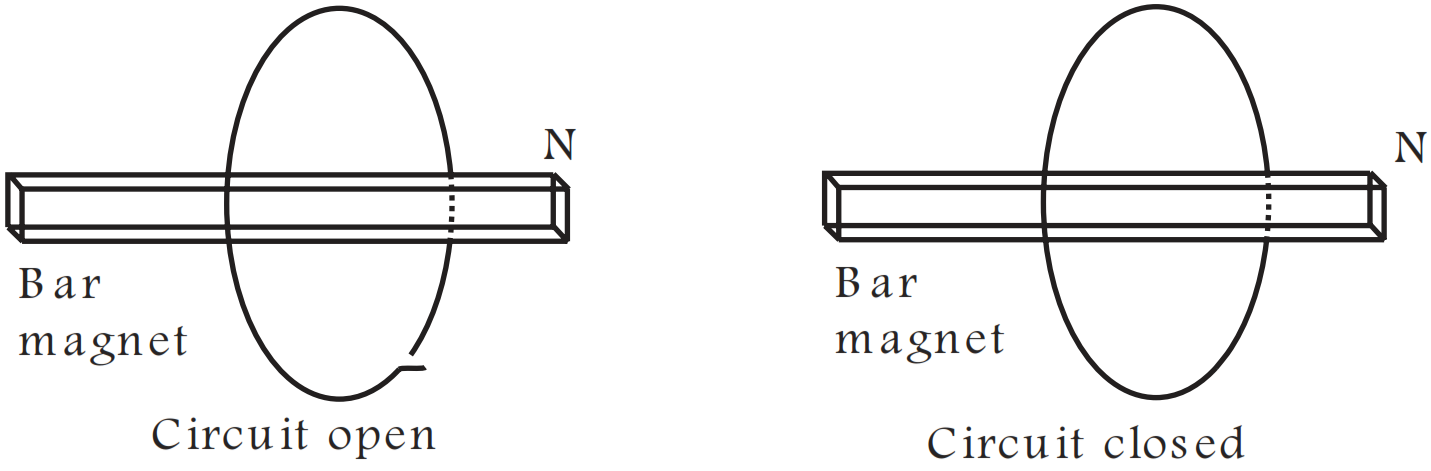
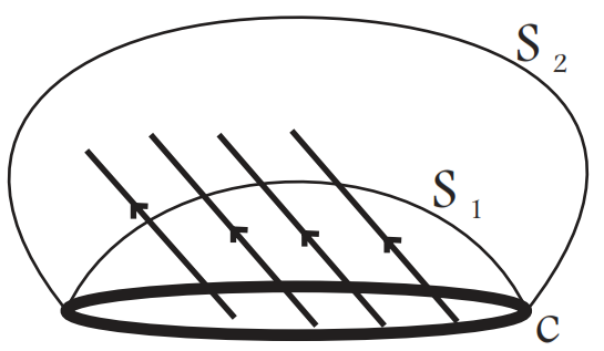
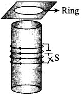
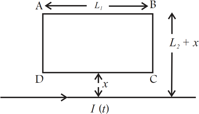
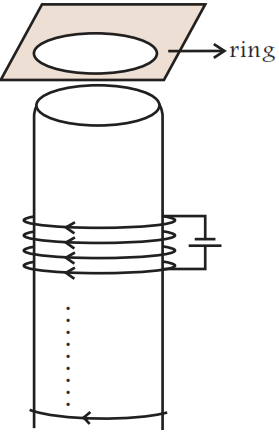
Predict the direction of induced current in the situations described by the following Figs. (a) to (f).
Answer
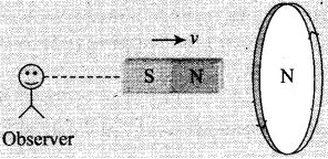
View full question & answer→The direction of the induced current in a closed loop is given by Lenz's law. The given pairs of figures show the direction of the induced current when the North pole of a bar magnet is moved towards and away from a closed loop respectively.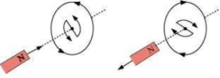
Using Lenz's rule, the direction of the induced current in the given situations can be predicted as follows:
Using Lenz's rule, the direction of the induced current in the given situations can be predicted as follows:
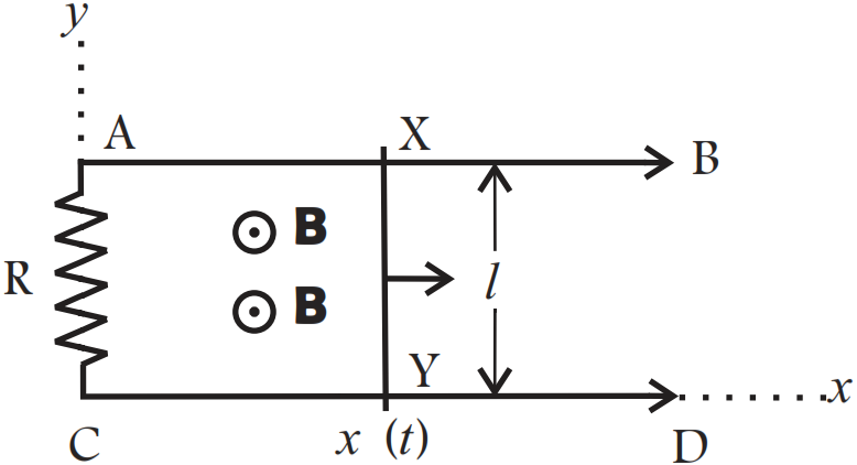
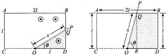
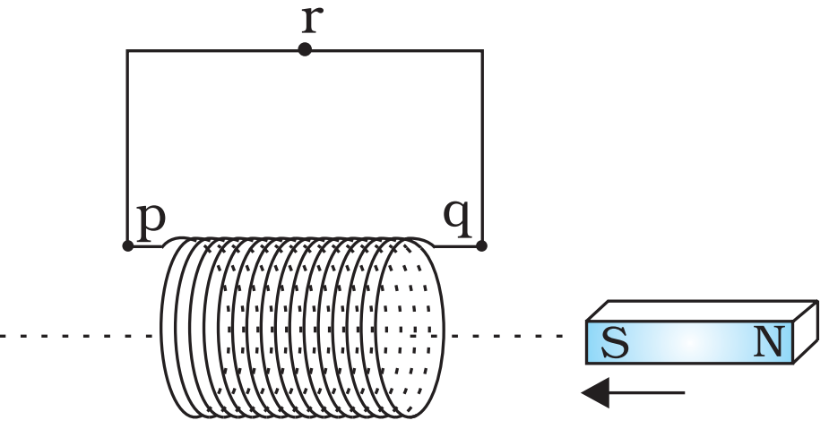
- The direction of the induced current is along qrpq.
- The direction of the induced current is along prqp.
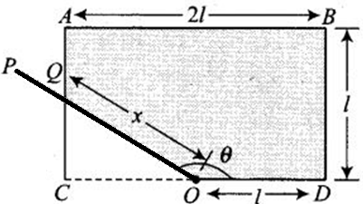
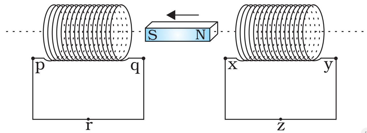
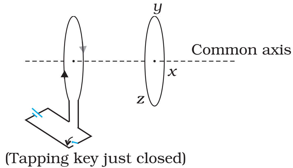
- The direction of the induced current is along yzxy.
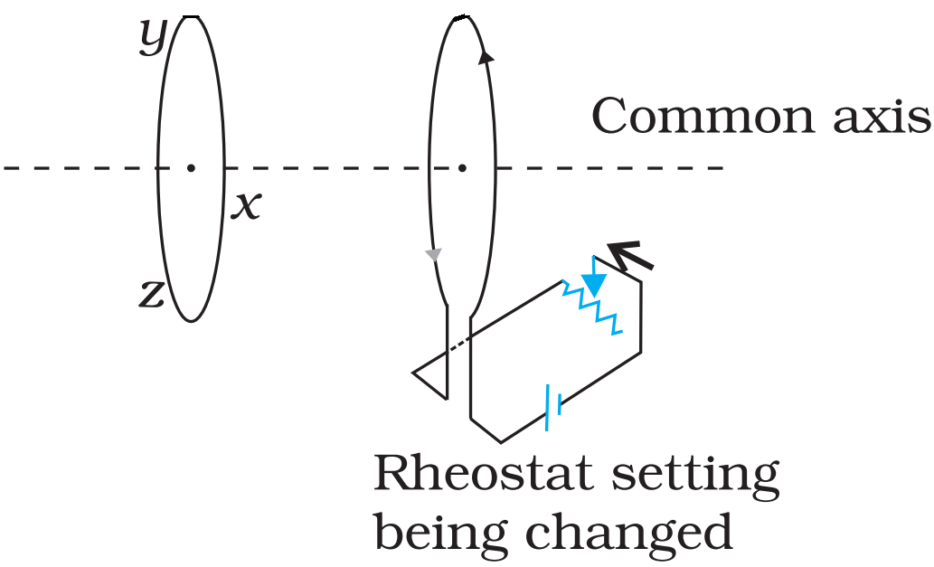
- The direction of the induced current is along zyxz.
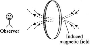
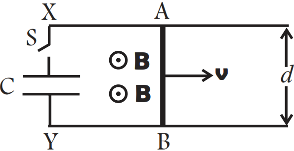
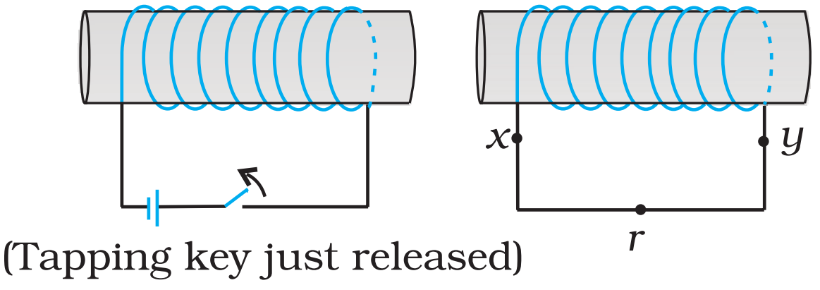
- The direction of the induced current is along xryx.
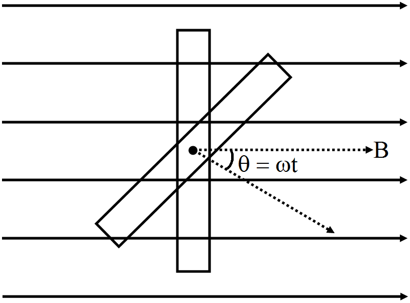
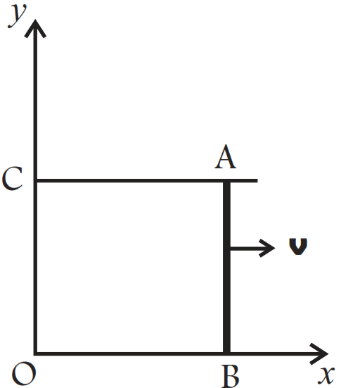
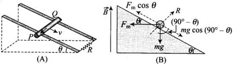
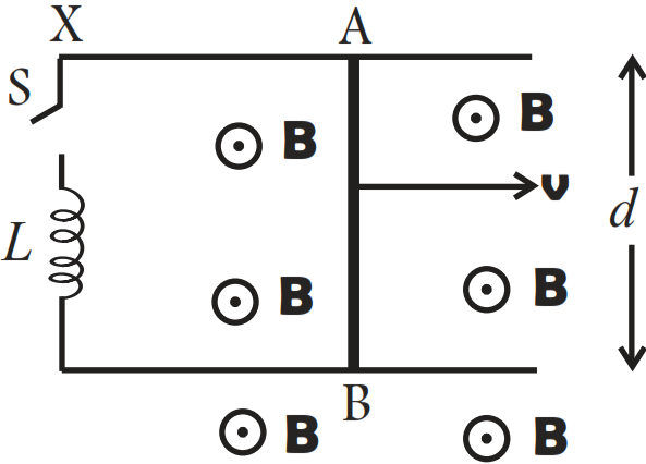
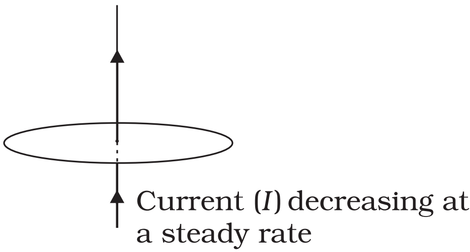
- No current is induced since the field lines are lying in the plane of the closed loop.