Questions · Page 3 of 3

3 Marks Question

Question 1013 Marks
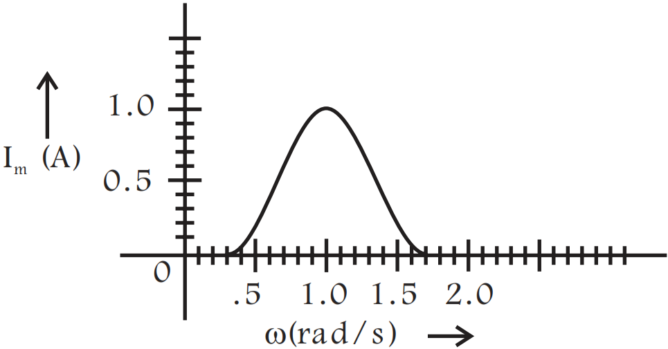
In series LCR circuit, the plot of $I_{max}$ vs $\omega$ is shown in Fig. Find the bandwidth and mark in the figure.
Answer
According top the given diagram,
Bandwidth $\Delta\omega=\omega_2-\omega_1$

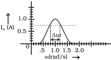
where $\omega_1$ and $\omega_2$ correspond to frequencies at which magnitude of current is $\frac{1}{\sqrt{2}}$ times of maximum value.
i.e., $\text{I}_\text{rms}=\frac{\text{I}_\text{max}}{\sqrt{2}}=\frac{1\text{A}}{\sqrt{2}}\approx0.7\text{A}$
From the graph these frequencies are $\omega_1=0.8\frac{\text{rad}}{\text{s}}$ and $\omega_2=1.2\frac{\text{red}}{\text{s}}.$
Thus, bandwidth, $\Delta\omega=\omega_1-\omega_2=1.2-0.8=0.4\frac{\text{rad}}{\text{s}}.$
View full question & answer
Question 1023 Marks
An AC voltage $V = V_m$​​​​​​​ is applied across a:
  1. Series RC circuit in which capacitive reactance is ‘a’ times the resistance in the circuit.
  2. Series RL circuit in which inductive reactance is ‘b’ times the resistance in the circuit.
Find the value of power factor of the circuit in each case.
Answer
Power factor $\cos\varphi=\frac{\text{R}}{\text{Z}},$ when $\text{Z}=\sqrt{\text{R}^2+\text{X}^2}$
  1. $\text{X = X}_{\text{C}} = \text{aR},$
$\therefore\text{Z}=\sqrt{\text{R}^2+(\text{aR})^2}=\text{R}\sqrt{1+\text{a}^2}$

$\therefore\cos\varphi=\frac{\text{R}}{\text{R}\sqrt{1+\text{a}^2}}=\frac{1}{\sqrt{1+\text{a}^2}}$
  1. $\text{X = X}_{\text{L}}=\text{bR},$
$\therefore\text{Z}=\sqrt{\text{R}^2+(\text{bR})^2}=\text{R}\sqrt{1+\text{b}^2}$

$\therefore\cos\varphi=\frac{\text{R}}{\text{R}\sqrt{1+\text{b}^2}}=\frac{1}{\sqrt{1+\text{b}^2}}$
View full question & answer
Question 1033 Marks
In the given circuit, the potential difference across the inductor L and resistor R are 200V and 150V respectively and the rms. value of current is 5A. Calculate (i) the impedance of the circuit and (ii) the phase angle between the voltage and the current.
Answer

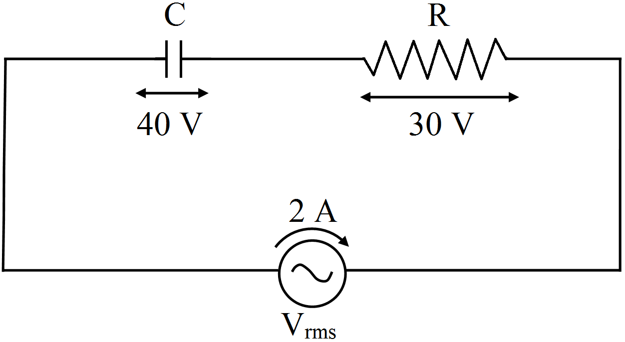
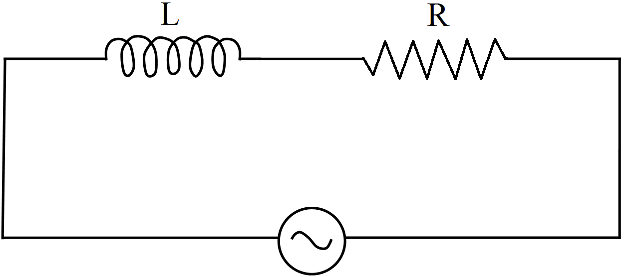
Voltage applied $\text{V}=\sqrt{\text{V}^2_\text{L}+\text{V}^2_\text{R}}=\sqrt{(200)^2+(150^2)}=250\text{V}$
Impedance of circuit, $\text{Z}=\frac{\text{V}}{\text{I}}=\frac{250}{5}=50\Omega$
Phase angle between voltage and current
$\tan\varphi=\frac{\text{x}_{\text{L}}}{\text{R}}=\frac{\text{V}_{\text{L}}}{\text{V}_{\text{R}}}=\frac{200}{150}=\frac{4}{3}$
$\varphi=\tan^{-1}\Big(\frac{4}{3}\Big)=53^{\circ}$
View full question & answer
Question 1043 Marks
Explain why the reactance offered by an inductor increases with increasing frequency of an alternating voltage.
Answer
The inductive reactance is given by $\text{X}_\text{L}=2\pi\text{fL}$, $X_L$ is proportional to the frequency and current is inversely proportional to the reactance. An inductor opposes the flow of current through it by developing a back emf according to Lenz’s law. If the current is decreasing, the polarity of the induced emf will be so as to increase the current and vice-versa.
Since, the induced emf is proportional to the rate of change of current.
View full question & answer
Question 1053 Marks
Find the time required for a 50Hz alternating current to change its value from zero to the rms value.
Answer
$\text{f}=50\text{Hz}$
$=\text{I}=\text{I}_0\sin\omega\text{t}$
Peak value $\text{I}=\frac{\text{I}_0}{\sqrt{2}}$
$\frac{\text{I}_0}{\sqrt{2}}=\text{I}_0\sin\omega\text{t}$
$\Rightarrow\ \frac{1}{\sqrt{2}}=\sin\omega\text{t}=\sin\frac{\pi}{4}$
$\Rightarrow\ \frac{\pi}{4}=\omega\text{t}$
Or $\text{t}=\frac{\pi}{400}$
$=\frac{\pi}{4\times2\pi\text{f}}=\frac{1}{8\text{f}}$
$=\frac{1}{8\times50}=0.0025\text{s}=2.5\text{ms}$
View full question & answer
Question 1063 Marks
In the given circuit, the value of resistance effect of the coil L is exactly equal to the resistance R. Bulbs $B_1$ and $B_2$ are exactly identical. Answer the following questions based on above information:
  1. Which one of the two bulbs lights up earlier, when key K is closed and why?
  2. What will be the comparative brightness of the two bulbs after sometime if the key K is kept closed and why?
Answer
  1. Bulb $B_2$ lights up earlier. The self-induction effect due to coil L in bulb $B_1$ arm does not allow the current to attain maximum value immediately on closing the circuit.
  2. Since the resistance effect of the coil L is equal to R and the self-induction effect in coil L will disappear after sometime, the current in both the arms will be equal. Hence, both the bulbs will glow with equal brightness after sometime.
View full question & answer
Question 1073 Marks
Calculate the following:
  1. Impedance of the given ac circuit.
  2. Wattless current of the given ac circuit.
Answer
  1. Potential difference across capacitance, $V_C = X_C\ I$
$\therefore$ Capacitive reactance,

$\text{X}_{\text{C}}=\frac{\text{V}_{\text{C}}}{\text{I}}=\frac{40}{2}=20\Omega$

Resistance, $\text{R}=\frac{\text{V}_{\text{R}}}{\text{I}}=\frac{30}{2}=15\Omega$

Impedance, $\text{Z}=\sqrt{\text{R}^2+\text{X}^2_{\text{C}}}=\sqrt{(15)^2+(20)^2}$

$=\sqrt{225+400}=\sqrt{625}\Omega=25\Omega$
  1.  


The phase lead $(\varphi)$ of current over applied voltage is

$\varphi=\frac{\text{X}_{\text{C}}}{\text{R}}$

Wattless Current, $\text{I}_{\text{wattless}}=\text{I}\sin\varphi=\text{I}\Big(\frac{\text{X}_{\text{C}}}{\text{Z}}\Big)$

$=2\times\frac{20}{25}\text{A}=1.6\text{A}$
View full question & answer
Question 1083 Marks
An AC source of voltage $\text{V = Vm}\sin\omega\text{t}$ is applied across a series LCR circuit. Draw the phasor diagrams for this circuit, when,
  1. Capacitive impedance exceeds the inductive impedance.
  2. Inductive impedance exceeds capacitive impedance.
Answer
  1. When $X_C > X_L$; the phasor diagram is shown in fig. (a).
  1. When $X_L > X_C;$ the phasor diagram is shown in fig. (b).
View full question & answer
Question 1093 Marks
The instantaneous current in an ac circuit is $\text{i}=0.5\sin314\text{t},$ what is (i) rms value and (ii) frequency of the current.
Answer
Given $\text{I}=0.5\sin314\text{t} \ ...(\text{i})$
Standard equation of current is $\text{I = I}_0\sin\omega\text{t} \ ...(\text{ii})$
Comparing (i) and (ii), we get $\text{I}_{0}=0.5\text{A},\omega=314$
Therefore,
  1. rms value $\text{I}_{\text{rms}}=\frac{\text{I}_0}{\sqrt{2}}=\frac{0.5}{\sqrt{2}}\text{A}=0.35\text{A}$
  2. Frequency $\text{v}=\frac{\omega}{2\pi}=\frac{314}{2\times3.14}=50\text{Hz}$
View full question & answer
Question 1103 Marks
An inductor 200mH, a capacitor $100\mu\text{F}$ and a resistor $10\Omega$ are connected in series to an a.c. source of 100V, having variable frequency.
  1. At what frequency of the applied voltage will the power factor of the circuit be 1?
  2. What will be the current amplitude at this frequency?
  3. Calculate the Q-factor of the circuit.
Answer
  1. Since the power factor $\varphi=1$ it means the phase difference between voltage and the current is zero.
This is possible when
$\text{wL}=\frac{1}{\omega\text{C}}$
$\omega^2=\frac{1}{\text{LC}}\Rightarrow\text{v}=\frac{1}{2\pi\sqrt{\text{LC}}}=35.58\text{Hz}$
  1. Current Amplitude, $\text{I}=\frac{\text{V}_{\text{eff}}}{\text{Z}}=\frac{\text{V}_{\text{eff}}}{\text{R}}=\frac{100}{10}=10\text{A}$ $(\therefore\text{Z = R})$
  2. Quality factor, $\text{Q}=\frac{1}{\text{R}}\sqrt{\frac{\text{L}}{}\text{C}}=4.47$
View full question & answer
Question 1113 Marks
A bulb rated 60W at 220V is connected across a household supply of alternating voltage of 220V. Calculate the maximum instantaneous current through the filament.
Answer
$\text{P}=60\text{W},\text{V}=220\text{V}=\text{E}$
$\text{R}=\frac{\text{V}^2}{\text{P}}=\frac{220\times220}{60}$
$=806.67$
$\in_0=\sqrt{2}\text{E}=1.414\times220$
$=311.08$
$\text{I}_0=\frac{\in_0}{\text{R}}=\frac{806.67}{311.08}$
$=0.385\approx0.39\text{A}$
View full question & answer
Question 1123 Marks
Consider the situation of the previous problem. Find the average electric field energy stored in the capacitor and the average magnetic field energy stored in the coil.
Answer
$\text{R}=300\Omega$
$\text{C}=20\mu\text{F}=20\times10^{-6}\text{F}$
$\text{L}=1\text{H},\text{Z}=500$ $(\text{from}\ 14)$
$\in_0=50\text{V},\text{I}_0=\frac{\text{E}_0}{\text{Z}}=\frac{50}{500}=0.1\text{A}$
Electric Energy stored in Capacitor $=\Big(\frac{1}{2}\Big)\text{CV}^2$
$=\Big(\frac{1}{2}\Big)\times20\times10^{-6}\times50\times50$
$=25\times10^{-3}\text{J}=25\text{mJ}$
Magnetic field energy stored in the coil $=\Big(\frac{1}{2}\Big)\text{LI}_0{^2}$
$=\Big(\frac{1}{2}\Big)\times1\times(0.1)^{2}$
$=5\times10^{-3}\text{J}=5\text{mJ}$
View full question & answer
Question 1133 Marks
A coil of inductance 5.0mH and negligible resistance is connected to the oscillator of the previous problem. Find the peak currents in the circuit for $\omega=100\text{s}^{-1},500\text{s}^{-1},1000\text{s}^{-1}.$
Answer
Inductance $=5.0\text{mH}=0.005\text{H}$
  1. $\omega=100\text{s}^{-1}$
$\text{X}_\text{L}=\omega\text{L}$

$=100\times\frac{5}{1000}=0.5\Omega$

$=\text{i}=\frac{\in_0}{\text{X}_\text{L}}=\frac{10}{0.5}=20\text{A}$
  1. $\omega=500\text{s}^{-1}$
$\text{X}_\text{L}=\omega\text{L}$

$=500\times\frac{5}{1000}=2.5\Omega$

$=\text{i}=\frac{\in_0}{\text{X}_\text{L}}=\frac{10}{2.5}=4\text{A}$
  1. $\omega=1000\text{s}^{-1}$
$\text{X}_\text{L}=\omega\text{L}$

$=1000\times\frac{5}{1000}=5\Omega$

$=\text{i}=\frac{\in_0}{\text{X}_\text{L}}=\frac{10}{5}=2\text{A}$
View full question & answer
Question 1143 Marks
The voltage and current in a series AC circuit are given by, $\text{V}=\text{V}_0\cos\omega\text{t}$ and $\text{i}=\text{i}_0\sin\omega\text{t}.$ What is the power dissipated in the circuit?
Answer
Power $=\text{I}_\text{rms}\text{E}_\text{rms}\cos\phi$
$\phi=\frac{\pi}{2}$ so $\text{P}=0.$
View full question & answer
Question 1153 Marks
A transformer has 50 turns in the primary and 100 in the secondary. If the primary is connected to a 220V DC supply, what will be the voltage across the secondary?
Answer

Transformer works upon the principle of induction which is only possible in case of AC.
Hence when DC is supplied to it, the primary coil blocks the Current supplied to it and hence induced current supplied to it and hence induced Current in the secondary coil is zero.
View full question & answer
Question 1163 Marks
In the given diagram, a coil B is connected to low voltage bulb L and placed parallel to another coil A as shown. Explain the following observations:
  1. Bulb lights.
  2. Bulb gets dimmer if the coil B moves upwards.
Answer
  1. Bulb lights up due to induced current in B because of change in flux linked with it as a consequence of continuous variation of magnitude of alternative current flowing in A.
  2. When coil B moves upward, the magnetic flux linked with B decreases and hence lesser current is induced in B.
View full question & answer
Question 1173 Marks
Prove that the power dissipated in an ideal resistor connected to an ac source is $\frac{\text{V}^2_{\text{eff}}}{\text{R}}.$
Answer
Power in ac circuit, P $=\text{V}_{\text{rms}}\text{i}_{\text{rms}}\cos\varphi$
As rms values of current and voltage are also caled effective values i.e.
$\text{P = V}_{\text{eff}}\text{I}_{\text{eff}}\cos\varphi \ ...(\text{i})$
But $\cos\varphi=\text{power factor}=\frac{\text{R}}{\text{Z}}$
In a purely resistive circuit Z $=\text{R},\cos\varphi=1$
and $\text{i}_{\text{eff}}=\frac{\text{V}_{\text{eff}}}{\text{Z}}=\frac{\text{V}_{\text{eff}}}{\text{R}}$
Substituting these value in (i), we get
$\text{P}=\text{V}_{\text{eff}}.\frac{\text{V}_{\text{eff}}}{\text{R}}\times1=\frac{\text{V}^2_{\text{eff}}}{\text{R}}$
View full question & answer
Question 1183 Marks
What is the power dissipated in an ac circuit in which voltage and current are given by $\text{V}=230\sin(\omega\text{t}+\frac{\pi}{2})$ and $\text{I}=10\sin\omega\text{t}?$
Answer
Power dissipated P $=\frac{1}{2}\text{V}_0\text{I}_0\cos\varphi$
Here, $\text{V}_0=230\text{V},\text{I}_0=10\text{A},\varphi=\frac{\pi}{2}$
$\therefore\text{P}=\frac{1}{2}\times230\times10\cos\frac{\pi}{2}=0$
View full question & answer
Question 1193 Marks
When a capacitor is connected in series LR circuit, the alternating current flowing in the circuit increases. Explain why.
Answer
Impedance of series LR circuit
$\text{Z}_1=\sqrt{\text{R}^2+\text{X}^2_{\text{L}}}$
When capacitor is also connected in circuit,
Then impedance
$\text{Z}_{\text{L}}=\sqrt{\text{R}^2+(\text{X}_{\text{L}}-\text{X}_{\text{C}})^2}$
Clearly impedance of circuit decreases $(Z_2 < Z_1)$, so the value of current $\text{I}=\frac{\text{v}}{\text{z}}\propto\frac{1}{\text{z}}$ in the circuit increases.
View full question & answer
Question 1203 Marks
An electric bulb is designed to operate at 12 volts DC. If this bulb is connected to an AC source and gives normal brightness, what would be the peak voltage of the source?
Answer
$\text{E}=12\text{volt}$
$\text{i}^2\text{Rt}=\text{i}^2_\text{rms}\text{RT}$
$\Rightarrow\ \frac{\text{E}^2}{\text{R}^2}=\frac{\text{E}^2_\text{rms}}{\text{R}^2}$
$\Rightarrow\ \text{E}^2=\frac{\text{E}_0^2}{2}$
$\Rightarrow\ \text{E}_0{^2}=2\text{E}^2$
$\Rightarrow\ \text{E}_0{^2}=2\times12^2=2\times144$
$\Rightarrow \text{E}_0=\sqrt{2\times144}=16.97\approx17\text{V}$
View full question & answer
Question 1213 Marks

Figure shows a typical circuit for a low-pass filter. An AC input $V_{i }= 10mV$ is applied at the left end and the output $V_0$ is received at the right end. Find the output voltage for ν = 10kHz, 1.0MHz and 10.0MHz. Note that as the frequency is increased the output decreases and, hence, the name low-pass filter.
Answer

$\text{V}_1=10\times10^{-3}\text{V}$ $\text{R}=1\times10^3\Omega$ $\text{C}=10\times10^{-9}\text{F}$
  1. $\text{X}_\text{C}=\frac{1}{\omega\text{C}}=\frac{1}{2\pi\text{fC}}$
$=\frac{1}{2\pi\times10\times10^3\times10\times10^{-9}}$
$=\frac{1}{2\pi\times10^{-4}}$
$=\frac{10^4}{2\pi}=\frac{5000}{\pi}$
$\text{Z}=\sqrt{\text{R}^2+\text{X}_\text{C}{^2}}$
$=\sqrt{\big(1\times10^3\big)^2+\Big(\frac{5000}{\pi}\Big)^2}$
$=\sqrt{10^6+\Big(\frac{5000}{\pi}\Big)^2}$
$\text{I}_0=\frac{\text{E}_0}{\text{Z}}=\frac{\text{V}_1}{\text{Z}}$
$=\frac{10\times10^{-3}}{\sqrt{10^6+\Big(\frac{5000}{\pi}\Big)^2}}$
  1. $\text{X}_\text{C}=\frac{1}{\omega\text{C}}=\frac{1}{2\pi\text{fC}}$
$=\frac{1}{2\pi\times10^5\times10\times10^{-9}}$
$=\frac{1}{2\pi\times10^{-3}}=\frac{10^3}{2\pi}=\frac{500}{\pi}$
$\text{Z}=\sqrt{\text{R}^2+\text{X}_\text{C}{^2}}$
$=\sqrt{\big(10^3\big)^{2}+\Big(\frac{500}{\pi}\Big)^2}$
$=\sqrt{10^6+\Big(\frac{500}{\pi}\Big)^2}$
$\text{I}_0=\frac{\text{E}_0}{\text{Z}}=\frac{\text{V}_1}{\text{Z}}$
$=\frac{10\times10^{-3}}{\sqrt{10^6+\Big(\frac{500}{\pi}\Big)^2}}$
$\text{V}_0=\text{I}_0\text{X}_\text{C}=\frac{10\times10^{-3}}{\sqrt{10^6+\Big(\frac{500}{\pi}\Big)^2}}\times\frac{500}{\pi}$
$=1.6124\text{V}\approx1.6\text{mV}$
  1. $\text{f}=1\text{MHz}=10^6\text{Hz}$
$\text{X}_\text{C}=\frac{1}{\omega\text{C}}=\frac{1}{2\pi\text{fC}}$
$=\frac{1}{2\pi\times10^6\times10\times10^{-9}}$
$=\frac{1}{2\pi\times10^{-2}}=\frac{10^2}{2\pi}=\frac{50}{\pi}$
$\text{Z}=\sqrt{\text{R}^2+\text{X}_\text{C}{^2}}$
$=\sqrt{\big(10^3\big)^{2}+\Big(\frac{50}{\pi}\Big)^2}$
$=\sqrt{10^6+\Big(\frac{50}{\pi}\Big)^2}$
$\text{I}_0=\frac{\text{E}_0}{\text{Z}}=\frac{\text{V}_1}{\text{Z}}$
$=\frac{10\times10^{-3}}{\sqrt{10^6+\Big(\frac{50}{\pi}\Big)^2}}$
$\text{V}_0=\text{I}_0\text{X}_\text{C}=\frac{10\times10^{-3}}{\sqrt{10^6+\Big(\frac{50}{\pi}\Big)^2}}\times\frac{50}{\pi}$
$\approx1.16\mu\text{V}$
  1. $\text{f}=10\text{MHz}=10^7\text{Hz}$
$\text{X}_\text{C}=\frac{1}{\omega\text{C}}=\frac{1}{2\pi\text{fC}}$
$=\frac{1}{2\pi\times10^7\times10\times10^{-9}}$
$=\frac{1}{2\pi\times10^{-1}}=\frac{10}{2\pi}=\frac{5}{\pi}$
$\text{Z}=\sqrt{\text{R}^2+\text{X}_\text{C}{^2}}$
$=\sqrt{\big(10^3\big)^{2}+\Big(\frac{5}{\pi}\Big)^2}$
$=\sqrt{10^6+\Big(\frac{5}{\pi}\Big)^2}$
$\text{I}_0=\frac{\text{E}_0}{\text{Z}}=\frac{\text{V}_1}{\text{Z}}$
$=\frac{10\times10^{-3}}{\sqrt{10^6+\Big(\frac{5}{\pi}\Big)^2}}$
$\text{V}_0=\text{I}_0\text{X}_\text{C}=\frac{10\times10^{-3}}{\sqrt{10^6+\Big(\frac{5}{\pi}\Big)^2}}\times\frac{5}{\pi}$
$\approx16\mu\text{V}$
View full question & answer
Question 1223 Marks
Suppose the frequency of the source in the previous example can be varied. (a) What is the frequency of the source at which resonance occurs? (b) Calculate the impedance, the current, and the power dissipated at the resonant condition.
Answer
(a) The frequency at which the resonance occurs is
$
\begin{aligned}
\omega_0 & =\frac{1}{\sqrt{L C}}=\frac{1}{\sqrt{25.48 \times 10^{-3} \times 796 \times 10^{-6}}} \\
& =222.1 rad / s \\
v_r & =\frac{\omega_0}{2 \pi}=\frac{221.1}{2 \times 3.14} Hz =35.4 Hz
\end{aligned}
$

(b) The impedance $Z$ at resonant condition is equal to the resistance:
$
Z=R=3 \Omega
$
The rms current at resonance is
$
=\frac{V}{Z}=\frac{V}{R}=\left(\frac{283}{\sqrt{2}}\right) \frac{1}{3}=66.7 A
$
The power dissipated at resonance is
$
P=I^2 \times R=(66.7)^2 \times 3=13.35 kW
$
You can see that in the present case, power dissipated at resonance is more than the power dissipated in Example 7.8.
View full question & answer
Question 1233 Marks
A sinusoidal voltage of peak value $283 V$ and frequency $50 Hz$ is applied to a series $L C R$ circuit in which $R =3 \Omega, L=25.48 mH$, and $C =796 \mu F$. Find (a) the impedance of the circuit; (b) the phase difference between the voltage across the source and the current; (c) the power dissipated in the circuit; and (d) the power factor.
Answer
(a) To find the impedance of the circuit, we first calculate $X_{ L }$ and $X_{ C }$.
$
\begin{array}{c}
X_L=2 \pi v L \\
=2 \times 3.14 \times 50 \times 25.48 \times 10^{-3} \Omega=8 \Omega \\
X_C=\frac{1}{2 \pi v C} \\
=\frac{1}{2 \times 3.14 \times 50 \times 796 \times 10^{-6}}=4 \Omega
\end{array}
$

Therefore,
$
\begin{aligned}
Z & =\sqrt{R^2+\left(X_L-X_C\right)^2}=\sqrt{3^2+(8-4)^2} \\
& =5 \Omega
\end{aligned}
$

(b) Phase difference, $\phi=\tan ^{-1} \frac{X_C-X_L}{R}$
$
=\tan ^{-1}\left(\frac{4-8}{3}\right)=-53.1^{\circ}
$
Since $\phi$ is negative, the current in the circuit lags the voltage across the source.

(c) The power dissipated in the circuit is
$
P=I^2 R
$
Now, $I=\frac{i_m}{\sqrt{2}}=\frac{1}{\sqrt{2}}\left(\frac{283}{5}\right)=40 A$
Therefore, $P=(40 A )^2 \times 3 \Omega=4800 W$

(d) Power factor $=\cos \phi=\cos \left(-53.1^{\circ}\right)=0.6$
View full question & answer
Question 1243 Marks
A resistor of $200 \Omega$ and a capacitor of $15.0 \mu F$ are connected in series to a $220 V , 50 Hz \ ac$ source. $(a)$ Calculate the current in the circuit; $(b)$ Calculate the voltage $\text{(rms)}$ across the resistor and the capacitor. Is the algebraic sum of these voltages more than the source voltage? If yes, resolve the paradox.
Answer
Given
$R=200 \Omega, C=15.0 \mu F =15.0 \times 10^{-6} F$
$V=220 V , v=50 Hz$
$(a)$ In order to calculate the current, we need the impedance of the circuit. It is
$Z =\sqrt{R^2+X_C^2}=\sqrt{R^2+(2 \pi v C)^{-2}}$
$ =\sqrt{(200 \Omega)^2+\left(2 \times 3.14 \times 50 \times 15.0 \times 10^{-6} F \right)^{-2}}$
$ =\sqrt{(200 \Omega)^2+(212.3 \Omega)^2}$
$ =291.67 \Omega$
Therefore, the current in the circuit is
$I=\frac{V}{Z}=\frac{220 V }{291.5 \Omega}=0.755 A$
$(b)$ Since the current is the same throughout the circuit, we have
$V_R=I R=(0.755 A )(200 \Omega)=151 V$
$V_C=I X_C=(0.755 A )(212.3 \Omega)=160.3 V$
The algebraic sum of the two voltages, $V_R$ and $V_C$ is $311.3 V$ which is more than the source voltage of $220 V$.
How to resolve this paradox?
As you have learnt in the text, the two voltages are not in the same phase.
Therefore, they cannot be added like ordinary numbers.
The two voltages are out of phase by ninety degrees.
Therefore, the total of these voltages must be obtained using the Pythagorean theorem:
$V_{R+C} =\sqrt{V_R^2+V_C^2}$
$ =220 V$
Thus, if the phase difference between two voltages is properly taken into account, the total voltage across the resistor and the capacitor is equal to the voltage of the source.
View full question & answer
3 Marks Question - Page 3 - Physics STD 12 Science Questions - Vidyadip