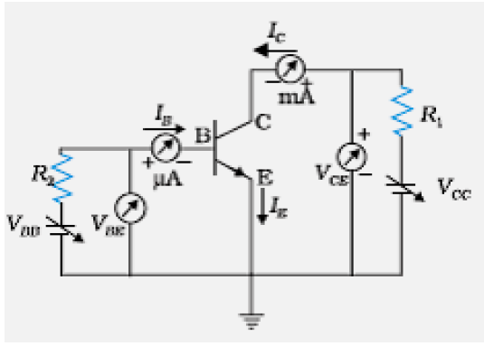
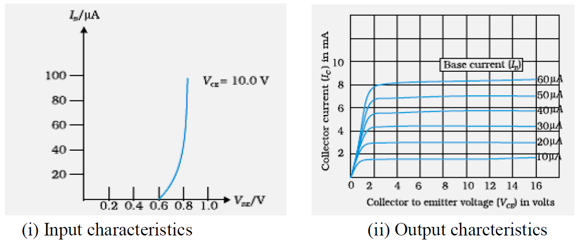
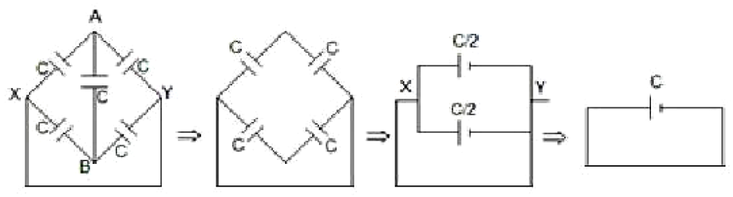
Questions · Page 2 of 3

3 Marks Question

Question 513 Marks
  1. In Young's double slit experiment, two slits are 1 mm apart, and the screen is placed 1 m away from the slits. Calculate the fringe width when light of wavelength 500 nm is used.
  2. What should be the width of each slit in order to obtain 10 maxima of the double slits pattern within the central maximum of the single slit pattern?
Answer
  1. $\beta = \frac{\lambda\text{D}}{\text{d}}$
$ = \frac{500\times10^{-9}\times1}{10^{-3}}$

$= 0.5\ mm or 5 x 10^{-4}m$​​​​​​​
  1. $\beta_{0} = \frac{2\lambda\text{D}}{\text{a}} = 10 \beta$
$\text{a} = \frac{2\times500\times10^{-9}\times1}{10\times5\times10^{-4}}$

$? =2 \times 10^{−4}m\ or\ 0.2\ mm.$
View full question & answer
Question 523 Marks
Draw a circuit diagram to study the input and output characteristics of an n-p-n transistor in common emitter configuration. Explain briefly how this arrangement is used to obtain the typical input/output characteristics of a transistor. Draw the graphs showing the nature of input/output curves.
Answer


For input characteristic, Keep $V_{CE}$ as fixed value. Study the dependence of $I_B$ and $V_{BE.}$
For output characteristic, Keep $I_B$ as constant. Study the dependence of $I_c$ on $V_{CE.}$​​​​​​​
View full question & answer
Question 533 Marks
A resistor of 100 $\Omega$ and a capacitor of $100 / \pi\mu\text{F}$ are connected in series to a 220 V, 50 Hz a.c. supply.
  1. Calculate the current in the circuit.
  2. Calculate the (rms) voltage across the resistor and the capacitor. Do you find the algebraic sum of these voltages more than the source voltage? If yes, how do you resolve the paradox?
Answer
  1. Current in the circuit $\text{I} = \frac{\text{V}}{\sqrt{\text{R}^{2} + \bigg(\frac{1}{\text{C}\omega}\bigg)^{2}}}$
$\text{I} = \frac{220}{\sqrt{100^{2} + \bigg(\frac{1}{\frac{100}{\pi}\times10^{-6}\times2\pi\times50}}\bigg)^{2}}$
$ = \frac{2.2}{\sqrt{2}}\text{A} = 1.55\text{A}$
  1. Voltage across the resistor$ = 100\times1.55 \text{V}$
$ = 155 \text{ volt}$
Voltage across the capacitor $ = 100\times1.55 \text{V}$
$ = 155 \text{ volt}$
Yes,
The sum of the two voltages is greater than 220 V but the voltage across the resistor and the capacitor are not in phase.
View full question & answer
Question 543 Marks
A 600 pF capacitor is charged by a 200 V supply. It is then disconnected from the supply and is connected to another uncharged 300 pF capacitor. Calculate how much electrostatic energy is lost in the process. What is the source of energy loss?
Answer
We have, energy stored $\frac{1}{2}\frac{\text{Q}}{\text{c}^{2}}$
and Equivalent Capacitance $= C_1 +C_2$
$=(600+300)\ pF$
Charge on the capacitor $= Q = 600 \times 200 \times 10^{-12}$
$= 12 \times 10^{-8} C$
Initial Energy $ = \frac{1}{2}\frac{\text{Q}^{2}}{\text{c}} = \frac{1}{2}\frac{\text{Q}^{2}}{600\times10^{-12}}$
Final Energy $= \frac{1}{2}=\frac{\text{Q}^{2}}{900\times10^{-12}}$
Loss in Energy $ =\frac{1}{2}\frac{144\times10^{-16}}{10^{-12}}\bigg[\frac{1}{600} - \frac{1}{900}\bigg]$
$ = 4 \times10^{-6}\text{J}$
The source of energy loss is the energy converted into heat due to sharing of charge between the two capacitors. (Also accept: heat produced).
View full question & answer
Question 553 Marks
  1. When an AC source is connected to an ideal inductor show that the average power supplied by the source over a complete cycle is zero.
  2. A lamp is connected in series with an inductor and an AC source. What happens to the brightness if the lamp when the key is plugged in and an iron rod is inserted inside the inductor? Explain.
Answer
  1. $\text{P}_{av} = \text{I}_{av}\text{x }\text{ e}_{av}\cos\phi$
For an ideal inductor, $\phi = \frac{\pi}{2}$

$\therefore\text{P}_{av} = \text{l}_{av} \text{x } \text{ e}_{av}\cos\frac{\pi}{2}$

$\text{P}_{av} = 0 .$
  1. Brightness decreases:
Because as iron rod is inserted inductance increases. Thus, current decreases and brightness decreases.
View full question & answer
Question 563 Marks
Two capacitors of capacitance $10\mu\text{F}$ and $20 \mu\text{F}$ are connected in series with a 6 V battery. After the capacitors are fully charged, a slab of dielectric constant (K) is inserted between the plates of the two capacitors. How will the following be affected after the slab is introduced:
  1. The electric field energy stored in the capacitors.
  2. The charges on the two capacitors.
  3. The potential difference between the plates of the capacitors.
Justify your answer.
Answer
The capacitance of both the capacitors increases by a factor K.
  1. New Electric field energy values are: = $\frac{1}{2}\text{k}(\text{c}_{1}\text{v}^{2}_{1}) \text{ and}\frac{1}{2}\text{k}(\text{c}_{2}\text{v}^{2}_{1}).$
  2. New charges are: =$\frac{1}{2}\text{KC}_{1}\text{V}_{1}\text{ and }\frac{1}{2}\text{KC}_{2}\text{V}_{2}.$
  3. New P.D values are: $V_1$ and $V_2$
(The battery remains connected to the capacitors)
Alternate Answer
  1. New Electric field energy values are: $\frac{1}{2}\frac{\text{Q}^{2}}{\text{KC}_{1}} \text{and } \frac{1}{2}\frac{\text{Q}^{2}}{\text{KC}_{2}}.$
  2. New charges are: Q and Q as before.
  3. New P.D values are: $\frac{\text{Q}}{\text{KC}_{1}} \text{and }\frac{\text{Q}}{\text{KC}_{2}}.$
View full question & answer
Question 573 Marks
A voltage $V = V_o$ sin $\omega\text{t}$ is applied to a series LCR circuit. Derive the expression for the average power dissipated over a cycle. Under what condition is (i) no power dissipated even though the current flows through the circuit, (ii) maximum power dissipated in the circuit?
Answer
Applied voltage $= V_o$ sin $\omega\text{t}$
Current in the circuit $=I_o$ sin $(\omega\text{t} - \phi)$
where $\phi$is the phase lag of the current with respect to the voltage applied, Hence instantaneous power dissipation
$ = \text{V}_{0} \sin \omega\text{t}\times\text{I}_{o}\sin(\omega\text{t} - \phi) $
$ = \frac{\text{V}_{0}\text{I}_{0}}{2}[2\sin\omega\text{t}.\sin(\omega\text{t} - \phi]$
$ = \frac{\text{V}_{0}\text{I}_{0}}{2}[\cos\phi - \cos(2\omega\text{t} - \phi]$
Therefore, average power for one complete cycle
= average of $ [ \frac{\text{V}_{0}\text{I}_{0}}{2}[\cos\phi - \cos(2\omega\text{t} - \phi]]$
The average of the second term over a complete cycle is zero.
Hence, average power dissipated over one complete cycle $ = \frac{\text{V}_{0}\text{I}_{0}}{2}\cos\phi$
Conditions:
  1. No power is dissipated when R = 0 $(\text{or }\phi = 90^{o} ) $
  2. Maximum power is dissipated when $X_L= X_C$​​​​​​​
Alternate Answer
$\omega\text{L} = \frac{1}{\text{wc}}(\text{or } \phi = 0).$
View full question & answer
Question 583 Marks
Derive an expression for the electric field intensity at a point on the equatorial line of an electric dipole of dipole moment $\overrightarrow{\text{P}}$and length 2a. What is the direction of this field?
Answer

$\text{E}_{+q} = \text{kq}/ (\text{r}^{2} + \text{a}^{2})\text{ and }\text{E}_{-q} =\text{Kq}/ (\text{r}^{2} + \text{a}^{2})$
The two Electric fields have equal magnitudes and their directions are as shown in diagram. Components along dipole axis get added up while normal components cancel each other.
$\therefore\text{E} = - [\text{E}_{-q} + \text{E}_{+q}]\cos\theta\hat{\text{ r}}\text{ so }\text{ E } = - \frac{\text{K}2\text{qa}}{[\text{r}^{2} + \text{a}^{2}]\frac{3}{2}}\hat{\text{r}}$
$ = \frac{\text{kp}}{[\text{r}^{2} + \text{a}^{2}]\frac{3}{2}}(\text{p} = 2 \text{qa}\hat{\text{r}}) = \frac{-1}{4\pi\in_{o}}\frac{\text{p}}{[\text{r}^{2} + \text{a}^{2}]\frac{3}{2}}$
$\therefore$ Direction of electric field is opposite to that of dipole moment.
View full question & answer
Question 593 Marks
  1. A parallel plate capacitor $(C_1)$ having charge Q is connected, to an identical uncharged capacitor $C_2$ in series. What would be the charge accumulated on the capacitor $C_2?$
  2. Three identical capacitors each of capacitance 3mF are connected, in tern, in series and in parallel combination to the common source of V volt. Find out the ratio of the energies stored in two configurations.
Answer
  1. Zero.
  2. We have $\text{C}_{series} = \frac{3\mu\text{F}}{3} =1 \mu\text{F}$
Also, $\text{C}_{parallel} =( 3 + 3 +3 ) =9 \mu\text{F}$

Energy stored $ = \frac{1}{2}\text{CV}^{2}$

$\therefore$Energy in series combination $ =\frac{1}{2}1 \times10^{-6}\times\text{V}^{2}$

Energy in parallel combination $ =\frac{1}{2}9 \times10^{-6}\times\text{V}^{2}$

$\therefore$ Ratio = 1:9.
View full question & answer
Question 603 Marks
  1. Explain briefly the process of emission of light by a Light Emitting Diode (LED).
  2. Which semiconductors are preferred to make LEDs and why?
  3. Give two advantages of using LEDs over conventional incandescent lamps.
Answer
  1. During Forward bias of LED, electrons move from n side to p side and holes move from p side to n side. During recombination, energy is released in the form of photons having energy hv of the order of band gap.
  2. Ga As/Ga As P.
Band gap should be 1.8 eV to 3 eV These materials have band gap which is suitable to produce desired visible light wavelengths.
  1. Low operational voltage, fast action, no warm up time required, nearly monochromatic, long life, ruggedness, fast on and off switching capacity.
View full question & answer
Question 613 Marks
  1. Mention two properties of soft iron due to which it is preferred for making an electromagnet.
  2. State Gauss's law in magnetism. How is it different from Gauss's law in electrostatics and why?
Answer
  1. Low coercivity and high permeability.
  2. The net magnetic flux through any closed surface is zero/
$\oint\text{B}.\text{ds} = 0 $

$\oint\text{E}.\text{ds} = \frac{\text{q}}{\in_{o}}$/The net electric flux through any closed surface is $\frac{1}{\in_{o}}$ times the net charge.

which indicates magnetic monopoles do not exist/ magnetic poles always exists in pairs.
View full question & answer
Question 623 Marks
Find the equivalent capacitance of the network shown in the figure, when each capacitor is of $1\mu\text{F}$. When the ends X and Y are connected to a 6 V battery, find out (i) The charge and (ii) The energy stored in the network.
Answer

The equivalent setup is:

Here $?_A = ?_B$(A & B are at the same potential) so the bridge capacitor can be removed.
  1. $\text{Q} = \text{CV} = 6 \mu\text{c}.$
  2. $\text{U} = \frac{1}{2}\text{qV} = 18 \mu\text{J}.$
View full question & answer
Question 633 Marks
How are electromagnetic waves produced? What is the source of energy of these waves? Draw a schematic sketch of the electromagnetic waves propagating along the + x-axis. Indicate the directions of the electric and magnetic fields. Write the relation between the velocity of propagation and the magnitudes of electric and magnetic fields.
Answer
Production: Electromagnetic waves are produced by "accelerated Charges‟.
The battery/Electric field that accelerates the charge carriers is the source of energy of em waves.
Schematic sketch/diagram.

$\text{c} = \frac{\text{E}}{\text{B}}$ $\overrightarrow{\text{E}}\times\overrightarrow{\text{B}}$ indicate the direction of propagation.
Directions of $\overrightarrow{\text{E}}$ Along $\overrightarrow{\text{y}}$ axis/Along ? axis
Directions of ? Along ? axis/Along ? axis
Relation: $\text{c} = \frac{\text{E}}{\text{B}}$.
View full question & answer
Question 643 Marks
An object is placed 15 cm in front of a convex lens of focal length 10 cm. Find the nature and position of the image formed. Where should a concave mirror of radius of curvature 20 cm be placed so that the final image is formed at the position of the object itself?
Answer
For lens $\frac{1}{\text{v}} - \frac{1}{\text{u}} = \frac{1}{\text{f}}$
$\frac{1}{\text{v}} - \frac{1}{-15} = \frac{1}{+10}$
$\frac{1}{\text{v}} + \frac{1}{15} = \frac{1}{10}$
$\therefore\text{v} = 30\text{cm}$
Nature of image- real, magnified
Final image formed will be at the object itself only if image formed by lens is at the position of centre of curvature of mirror.
$\therefore\text{D} = (30 + \text{R})\text{cm} =(30 +20)\text{cm} = 50 \text{cm}.$
(Distance of mirror from lens).
View full question & answer
Question 653 Marks
What is space wave propagation? State the factors which limit its range of propagation. Derive an expression for the maximum line of sight distance between two antennas for space wave propagation.
Answer
Space Wave Propagation: The mode of propagation in which radio waves travel, along a straight line, from the transmitting to the receiving antenna. Limiting Factors:
  1. Curvature of the earth.
  2. Insufficient height of the receiving antenna.
Derivation:
From the figure, we have $(\text{R} + \text{h})^{2} = \text{R}^{2} + \text{d}^{2}$ Or $2\text{Rh}\cong\text{d}^{2}(\text{as}\text{h}^{2} < < 2\text{Rh})$ $\therefore , \text{d} = \sqrt{2\text{Rh}}$ For a transmitting antenna of height$\text{h}_{T}$, and a receiving antenna of height$\text{h}_{R}$, the maximum line of sight distance becomes, $\text{d}_{M} = \sqrt{2\text{Rh}_{T}} + \sqrt{2\text{Rh}_{R}}$.
View full question & answer
Question 663 Marks
  1. Derive the mathematical expression for law of radioactive decay for a sample of a radioactive nucleus.
  2. How is the mean life of a given radioactive nucleus related to the decay constant?
Answer
  1. Let there be $\text{N}_{0}$ radioactive nuclei at t =0.
If N is the number of nuclei left over at t=t, we have

$\frac{-\text{dN}}{\text{dt}}\propto\text{N}$

Or $\frac{-\text{dN}}{\text{dt}} = \lambda\text{N}(\lambda =\text{decay constant })$

$\therefore\frac{\text{dN}}{\text{N}} = -\lambda\text{dt}$

Or $l \text{nN} = - \lambda\text{t} + constant $

$\therefore \text{ At } \text{t} = 0 , $ we have

$l\text{nN}_{0} = constant $

$l \text{nN} = - \lambda\text{t} + l\text{nN}_{0}$

Or $l\text{n}(\frac{\text{N}}{\text{N}_{0}}) = -\lambda\text{t}$

$\therefore \text{N} = \text{N}_{0}\text{e}^{-\lambda\text{t}}$
  1. Mean life $ = \frac{1}{\text{decay constant }}$
Alternate Answer

$\tau = \frac{1}{\lambda}$.
View full question & answer
Question 673 Marks
  1. Distinguish between a conductor and a semi conductor on the basis of energy band diagram.
  2. The following figure shows the input waveforms (A, B) and the output waveform (Y) of a gate. Identify the gate, write its truth table and draw its logic symbol.
Answer


  1. The gate is a NAND gate. Truth Table of NAND gate.

Logic Symbol:
View full question & answer
Question 683 Marks
Two identical cells of emf 1.5 V each joined in parallel supply energy to an external circuit consisting of two resistances of 7 $\Omega$ each joined in parallel. A very high resistance voltmeter reads the terminal voltage of cells to be 1.4 V. Calculate the internal resistance of each cell.
Answer
We have, for a single cell,
$\text{r} = \bigg(\frac{\text{E}}{\text{V}} - 1 \bigg)\text{R}$
$\therefore$ For the parallel combination, as given in the question.
$\frac{\text{r}}{2} = \bigg(\frac{\text{E}}{\text{V} - 1 }\bigg)\frac{\text{R}}{2}$
$\therefore\text{r} = \bigg(\frac{1.5}{1.4} - 1 \bigg)\times\text{7}\Omega$
$ = \frac{0.1}{1.4}\times7\Omega$
$ = 0.5\Omega$
Alternate Answer

$\text{I} =\frac{\text{V}}{(\text{R} / 2 )}$
And $\text{E} = \text{V} - \text{I}(\text{r}/ 2 )$
This gives $\text{I} = \frac{1.4}{7/2}\text{A} = 0.4\text{A}$
$\therefore\frac{\text{r}}{2} = \frac{1.5 - 1.4}{0.4} = 0.25$
$\therefore\text{r} = 0.5\Omega$.
View full question & answer
Question 693 Marks
  1. A screen is placed at a distance of 100 cm from an object. The image of the object is formed on the screen by a convex lens for two different locations of the lens separated by 20 cm. Calculate the focal length of the lens used.
  2. A converging lens is kept coaxially in contact with a diverging lens - both the lenses being of equal focal length. What is the focal length of the combination?
Answer
  1. For first position of the lens, we have
$\frac{1}{\text{f}} = \frac{1}{\text{y}} -\frac{1}{(-\text{x})}$

For second position of the lens, we have
$\frac{1}{\text{f}} = \frac{1}{\text{y - 20 }} -\frac{1}{(-(\text{x + 20 )})}$
$\frac{1}{\text{y}} +\frac{1}{\text{x}} =\frac{1}{(\text{y - 20)}} + \frac{1}{(\text{x + 20)}}$
$\frac{\text{x + y }}{\text{xy}} =\frac{(\text{x + 20)} + (\text{y - 20 )}}{(\text{y - 20 )}(\text{x + 20 )}}$
$\therefore\text{xy} = (\text{y - 20) }(\text{x + 20})$
$ = \text{xy} - 20 \text{x +20}\text{y - 400 }$
$\therefore\text{x - y } = - 20 $
Also , x + y =100
$\therefore$ x = 40 cm
and y = 60 cm
$\therefore\frac{1}{\text{f}} = \frac{1}{60} - \frac{1}{-40} =\frac{2+3}{120} =\frac{5}{120}$
$\therefore\text{f} = 24 \text{cm}$
Alternate Answer
We have
$\text{f} = \frac{\text{D}^{2} - \text{d}^{2}}{4\text{D}}$
$ = \frac{100^{2} - 20 ^{2}}{4\times100}$
$ =\frac{120\times80}{400}$
= 24 cm.
Alternate Answer
For the two positions of the lens, the values of the magnitudes of u and v, get interchanged.
Hence, $| \text{u + v}| = 100$
$| \text{u - v}| = 20 , $
This gives $| \text{u}| = 60 |\text{v}| = 40 $
$\therefore\text{f} = 24 \text{ cm}$
Alternate Answer

$2\text{x} + 20 = 100$
$\therefore\text{x} = 40 \text{ cm}$
For lens at position $L_1; \text{u} = -\text{x} =- 40 \text{cm} $
$\text{v} = 20 + 40 = 60\text{ cm}$
This gives f = 24 cm.
  1. For combination of two lenses in contact.
Net Power of combination,
$P = P_1 + P_2$
$P_1 = +P , P_2 = -P$
So P= 0 and F= infinite
Alternate Answer
$\frac{1}{\text{F}} = \frac{1}{\text{f}_{1}} + \frac{1}{\text{f}_{2}}$
$ = \frac{1}{\text{f}} + (\frac{-1}{\text{f}}) = 0 $
F = infinite.
View full question & answer
Question 703 Marks
  1. Name two important processes that occur during the formation of a pn junction.
  2. Draw the circuit diagram of a full wave rectifier along with the input and output waveforms. Briefly, explain how the output voltage/current is unidirectional.
Answer
  1. Diffusion and Drift:
    1. Appearance of a BARRIER POTENTIAL across the junction.
    2. Formation of a DEPLETION REGION on either side of the junction.
  2. Circuit diagram:

Input and Output waveforms.


Because of (i) The use of the centre tap transformer and (ii) The manner in which the load is connected, the voltage across/current through, the load has the same direction during both half's of the input wave.
View full question & answer
Question 713 Marks
Using truth tables of AND gate and NOT gate show that NAND gate is an AND gate followed by a NOT gate. Hence write the truth table of NAND gate.
Why are NAND gates called ‘Universal Gates’?
Answer
A B Output of AND gate
(Input of NOT gate)
Output of NOT gate
0 0 0 1
0 1 0 1
1 0 0 1
1 1 1 0
Truth table of NAND Gate
A B Y
0 0 1
0 1 1
1 0 1
1 1 0
NAND gate is called universal gate because all other basic gates like AND, OR, NOT gate, can be realised by using NAND gates only.
View full question & answer
Question 723 Marks
  1. Describe the working of photodiode by drawing the circuit diagram.
  2. Draw the characteristics of a photodiode for different illumination intensities.
  3. Why is photodiode operated in reverse bias even though the reverse bias current is much weaker than the current in forward bias?
Answer
  1.  
  1. When light with energy $\text{hv} > \text{(?????? ???)} \text{?}_{?}$ falls on photodiode, electron-hole pairs are generated.
  2. Due to electric field at the junction, electrons and holes are separated before they combine.
  3. Electrons are collected on n-side and holes are collected on p-side giving rise to an emf and current flows in external load.
  1.  
  1. It is easier to observe the change in the current, with change in the light intensity, when reverse bias is applied.
View full question & answer
Question 733 Marks
  1. Draw a schematic diagram of a reflecting telescope.
  2. State the advantages of reflecting telescope over refracting telescope.
Answer
  1.  
  1. Advantages:
  1. There is no chromatic aberration in a mirror.
  2. Brighter image.
  3. High resolving Power.
  4. Large light gathering power.
  5. Large magnifying power.
View full question & answer
Question 743 Marks
Explain briefly, with the help of a circuit diagram, the transistor action of npn transistor in CE configuration. Draw the typical shapes of input and output characteristics.
Answer

Transistor works only when its emitter-base junction is forward biased and collector-emitter junction is reversed biased. Due to this the majority charge carriers from the emitter, accelerate to collector side and create $?_?,?_?$ and $?_?$ such that $?_?= ?_?+ ?_{?.}$​​​​​​​

View full question & answer
Question 753 Marks
Half life of $^{238}\text{U}_{92}$against$\alpha$ decay is $4.5 \times 10^{9}$years. Calculate the activity of Ig sample of$^{238}\text{U}_{92}$? Given Avogadro's number $= 6 \times 10^{26}$atoms/kmol.
Answer
Activity, R = λN
$ = \frac{0.693}{\text{T}_{1/2}}\text{N}$
Activity ( R ) $ = \frac{0.693}{1.42\times10^{17}}\times\text{N}$
Number of nuclei present in 1 gram sample of $^{238}_{92}\text{U} = 2503\times10^{20}$
$\Rightarrow\text{R} = \frac{0.693}{1.42\times10^{17}}\times\frac{6.0\times10^{26}}{238\times10^{3}}\text{s}^{-1}$
$ = 1.23\times10^{4}\text{s}^{-1}$.
View full question & answer
Question 763 Marks
Draw a schematic arrangement for winding of primary and secondary coils in a transformer with the two coils on separate limbs of the core. State its underlying principle and find the relation between the primary and secondary voltages in terms of the number of turns of the primary and secondary windings. How are the currents in the primary and secondary coils related to the voltages in the case of an ideal transformer?
Answer

Alternate Answer

When the current through the primary coil changes, the magnetic flux through the secondary changes. This produces an induced emf in the secondary coil/it works on mutual induction.
$\varepsilon_{s} = -\text{N}_{s}\frac{\text{d}\varphi}{\text{dt}}$
$\varepsilon_{p} = -\text{N}_{p}\frac{\text{d}\varphi}{\text{dt}}$
$\frac{\varepsilon_{s}}{\varepsilon_{p}} = \frac{\text{N}_{s}}{\text{N}_{p}}$
$i_{s}\varepsilon_{s} = i_{p} \varepsilon_{p}$ (for ideal transformer)
$\frac{i_{s}}{i_{p}} = \frac{\varepsilon_{p}}{\varepsilon_{s}}.$
View full question & answer
Question 773 Marks
  1. Write three characteristic properties of nuclear force.
  2. Draw a plot of potential energy of a pair of nucleons as a function of their separation. Write two important conclusions that can be drawn from the graph.
Answer
  1. Characteristic properties of Nuclear force:
  1. Short range force.
  2. Saturation forces.
  3. Very Strong force.
  4. Charge independent.
  1.  

Conclusions:
  1. Nuclear force is attractive for distance larger than $r_{o.}$​​​​​​​
  2. Nuclear force is repulsive if two nucleons are separated by distance less than $r_{o.}$
  3. Nuclear force decreases very rapidly for $r > r_{o.}$​​​​​​​
  4. Potential energy is minimum at $r_{o.}$ /Equilibrium position.
View full question & answer
Question 783 Marks
  1. Describe briefly three experimentally observed features in the phenomenon of photoelectric effect.
  2. Discuss briefly how wave theory of light cannot explain these features.
Answer
  1.  
  1. There is no emission of photoelectrons i.e. no current if the frequency of the incident radiation is below a certain minimum value however large may be the intensity of the light.
  2. The current varies directly with the intensity of the incident radiation.
  3. The current becomes zero at a certain value of negative potential, applied at the anode , this is known as stopping potential.
  4. The value of stopping potential increases with the increase in the frequency of the incident radiation.
  5. Maximum kinetic energy of the photo electrons does not depend upon intensity of light.
  6. Maximum kinetic energy of photoelectron increases with the frequency of the incident radiation.
  7. The process of photoelectric emission is instantaneous.
  1. It fails to explain why:
  • The photo electric emmission is instantaneous.
  • There exists a threshold frequency for a given metal.
  • The maximim KE of photoelectrons is independent of the intensity of incident radiation.
View full question & answer
Question 793 Marks
Define the electric resistivity of a conductor.
Plot a graph showing the variation of resistivity with temperature in the case of a (a) conductor, (b) semiconductor.
Briefly, explain, how the difference in the behaviour of the two can be explained in terms of number density of charge carriers and relaxation time.
Answer
Resistivity of a conductor is defined as the resistance of a material (of a Conductor) of unit length and unit area of cross section.
Alternate Answer

In conductor with increase in temperatures, relaxation time decreases, but number density of charge carriers is not dependent on temperature. Hence,$\rho$ increases.
In semiconductors number density of charge carriers increases with temperature, it dominates the decrease in relaxation time. Hence, $\rho$ decreases.
View full question & answer
Question 803 Marks
  1. For a given a.c.,$\text{i} = \text{i}_{m}\sin\omega\text{t},$ show that the average power dissipated in a resistor R over a complete cycle is $\frac{1}{2}\text{i}_{m}^{2}\text{R}.$
  2. A light bulb is rated at 100 W for a 220 V a.c. supply. Calculate the resistance of the bulb.
Answer
  1. From graph of $i^2 – t$
Average power consumed in resistor R

$\text{P}_{av} = \frac{1}{\int_{0}^{T}\text{dt}}.\int_{0}^{T}\text{i}^{2}\text{R dt}$

$ = \frac{\text{i}_{m}^{2}\text{R}}{\text{T}}\int_{0}^{T}\sin^{2}\omega\text{t }\text{ dt} - - - - - (1)$

$ = \frac{\text{i}_{m}^{2}\text{R}}{2\text{T}}\int_{0}^{T}(1 -\cos2\omega\text{t})\text{dt}$


$ = \frac{\text{i}_{m}^{2}\text{R}}{2\text{T}}\bigg[\int_{0}^{T}\text{dt} - \int_{0}^{T}\cos2\omega\text{t }\text{ dt}\bigg] - - - - - (2)$

$ =\frac{\text{i}_{m}^{2}\text{R}}{2\text{T}}[\text{T} - 0 ]$
$ = \frac{\text{i}_{m}^{2}\text{R}}{2}$
  1. In case of ac
$\text{P}_{av} =\frac{\text{V}_{rms}^{2}}{\text{R}} = \frac{\text{V}_{eff}^{2}}{\text{R}}$

$\Rightarrow\text{R} = \frac{\text{V}_{rms}^{2}}{\text{P}_{av}}$

$ = \frac{220\times220}{100}$

$ = 484\Omega.$
View full question & answer
Question 813 Marks
A series LCR circuit is connected to an ac source. Using the phasor diagram, derive the expression for the impedance of the circuit. Plot a graph to show the variation of current with frequency of the source, explaining the nature of its variation.
Answer


Resultant potential across LCR
$\text{V}^{2} = \text{V}^{2}_{\text{R}} + (\text{V}_{L} - \text{V}_{c} ) ^{2}$
$\text{V}_{R} = \text{iR},\text{V}_{L} = \text{i}\text{X}_{L},\text{V}_\text{c} = \text{i X}_{c}$
On solving
$\text{Z} = \sqrt{\text{R}^{2} + (\text{X}_{L} - \text{X}_{C})^{2}}$

With increase in ω, current first increases (up to $ω_o$ ) and then decreases.
View full question & answer
Question 823 Marks
A 0’5 m long metal rod PQ completes the circuit as shown in the figure. The area of the circuit is perpendicular to the magnetic field of flux density 0-15 T. If the resistance of the total circuit is 3Ω, calcularod in the direction as indicated with a constant speed ofte the force needed to move the rod in the direction as indicated with a constant speed of 2ms−1.
Answer
Method I
$\text{E} = \text{B} $ 1 v
$\text{I} =\frac{\text{B1v}}{\text{R}} = \text{I} = 0.5\text{A}$
$\text{F} = \text{B}$ I 1
Calculation of $\text{F} = 3.75\times10^{-3}\text{N}$.
Method II
$\text{F} = \frac{\text{B}^{2}1^{2}\text{v}}{\text{R}}$
Correct substitution and calculation of $\text{F} = 3.75\times10^{-3}\text{N}$.
View full question & answer
Question 833 Marks
When an inductor L and a resistor R in series are connected across a 12 V, 50 Hz supply, a current of 0.5 A flows in the circuit. The current differs in phase from applied voltage by $\pi/3$ radian. Calculate the value of R.
Answer
Method – I
$\text{Z} =\text{E}/\text{I}$
Calculation of $\text{Z} =\frac{12}{0.5}= 24\Omega$
$\cos\phi = \frac{\text{R}}{\text{Z}}$
Calculation of R = 12Ω.
Method – II
$\text{Z} = \text{E}/\text{I}$
Z = 24Ω
$\tan \phi = \frac{\text{X}_{L}}{\text{R}}$
R = 12Ω.
View full question & answer
Question 843 Marks
A source of ac voltage $ v= v_0 \sin\omega t$, is connected across a pure inductor of inductance L. Derive the expressions for the instantaneous current in the circuit. Show that average power dissipated in the circuit is zero.
Answer
Given $V=V_0\sin\omega t$
$V=L\frac{di}{dt}\Rightarrow di=\frac{V}{L}dt$

$\therefore\text{ }di=\frac{\text{V}_0}{L}\sin\omega t\text{ }dt$
Integrating $i=-\frac{\text{V}_0}{wL}\cos\omega t$
$\therefore\text{}i=-\frac{\text{V}_0}{wL}\sin(\pi/2-\omega t)=I_0\sin(\pi/2-\omega t)$
where $I_0=\frac{V_0}{wL}$
Average power
$P_{av}=\int\limits_{0}^{T}vi\text{ }dt$
$=\frac{-V_0^2}{wL}\int_0^T\sin\omega t\cos\omega t\text{ }dt$
$=\frac{-V_0^2}{wL}\int_0^T\sin(2\text{ }\omega t)\text{ }dt$
= 0
View full question & answer
Question 853 Marks
  1. Find the value of the phase difference between the current and the voltage in the series LCR circuit shown below. Which one leads in phase: current or voltage?
  2. Without making any other change, find the value of the additional capacitor $C_1,$ to be connected in parallel with the capacitor C, in order to make the power factor of the circuit unity.
Answer
  1. $X_L=\omega_L=(1000\times100\times10^{-3})\Omega=100\Omega$
$X_C=\frac{1}{\omega C}=\bigg(\frac{1}{1000\times2\times10^{-6}}\bigg)\Omega=500\Omega$
Phase angle
$\tan\Phi=\frac{X_L-X_C}{R}$
$\tan\Phi=-\frac{\pi}{4}$
As $X_C>X_L$ (phase angle is negative), hence current leads voltage
  1. To make power factor unity
$X_{C'}>X_L$
$\frac{1}{WC'}=100$
$C'=10\mu\text{F}$
$C'=C+C_1$
$10=2+C_1$
$C_1=8\mu\text{F}$
View full question & answer
Question 863 Marks
An inductor L of inductance XL is connected in series with a bulb B and an ac source. How would brightness of the bulb change when (i) number of turns in the inductor is reduced, (ii) an iron rod is inserted in the inductor and (iii) a capacitor of reactance $X_C = X_L$ is inserted in series in the circuit. Justify your answer in each case.
Answer
  1. Increases
$\text{X}_{L} = \omega_{L}$

As number of turns decreases, L decreases, hence current through bulb increases. /voltage across bulb increases.
  1. Decreases
Iron rod increases the inductance, which increases $X_L,$ hence½ current through the bulb decreases/voltage across bulb decreases.
  1. Increases
condition $(X_C = X_L)$ the current through the bulb will become maximum/increase.
View full question & answer
Question 873 Marks
In a series LCR circuit connected to an ac source of variable frequency and voltage v $v_m= \sin, $ draw a plot showing the variation of current (I) with angular frequency ($\omega$) for two different values of resistance R1 and R2(R1 > R2 ). Write the condition under which the phenomenon of resonance occurs. For which value of the resistance out of the two curves, a sharper resonance is produced? Define Q-factor of the circuit and give its significance.
Answer

At certain frequency $\omega$, the flow of current through the series combination
$\text{I}_{m} = \frac{\text{v}_{m}}{\sqrt{\text{R}^{2} + (\text{x}_{L} - \text{x}_{C}^{2}})}$
Where $X_L = \omega_{L}$
and
$\text{X}_{C} = \frac{1}{\omega\text{C}}.$
Condition of resonance – If systemis (LCR) of natural frequency $\omega_{0}$ is driven by an energy source at a frequency $\omega$, the amplitude of the current flow increases, however the amplitude of the current rises to its maximum value, if frequency of the energy source becomes exactly equal to the natural frequency.
For resistance $R_2 < R_1$, series LCR shows a sharp resonance.
Q-factor – The ratio of reactance (either inductive or capacitive) at natural frequency to the resistance of the current is called Q - factor
$\text{Q} = \frac{\text{X}_{L}}{\text{R}} = \frac{\omega_{0}\text{L}}{\text{R}}$

Significance:
  1. If resistance R is low or inductance L is large then Q – factor is large and the circuit is more selective.
  2. If resonance is less sharp, tunning of the circuit will not be good.
View full question & answer
Question 883 Marks
The figure shows a series LCR circuit with L = 5.0 H, C = 80 $\mu$F, R = 40 W connected to a variable frequency 240V source. Calculate
  1. The angular frequency of the source which drives the circuit at resonance.
  2. The current at the resonating frequency.
  3. The rms potential drop across the capacitor at resonance.
Answer
  1. $\omega = \frac{1}{\sqrt{\text{LC}}}$
$ = \frac{1}{\sqrt{5\times80\times10^{-6}}} = 50\text{radian / s }$
  1. Current at resonance
$\text{I}_{rms} = \frac{\text{V}_{rms}}{\text{R}} = \frac{240}{40}\text{A} = 6\text{A}$
  1. $V_{rms}$ across capacitor
$\text{V}_{rms} = \text{I}_{rms}\text{X}_{c}$

$ = 6\times\frac{1}{50\times80\times10^{-6}}\text{V}$

$ = \frac{6\times10^{6}}{4\times10^{3}}\text{V} = \frac{6000}{4}\text{V} = 1500\text{V}.$
View full question & answer
Question 893 Marks
An inductor 200 mH, capacitor 500 µF, resistor 10Ω are connected in series with a100 V, variable frequency a.c. source. Calculate the
  1. Frequency at which the power factor of the circuit is unity.
  2. Current amplitude at this frequency.
  3. Q-factor.
Answer
  1. $\omega = \frac{1}{\sqrt{\text{LC}}}$
$ = \frac{1}{\sqrt{200\times10^{-3}\times500\times10^{-6}}} = 100 \text{ radian s }^{-1}$

$\big(\text{or } \text{ v} = \frac{\omega}{2\pi} = \frac{50}{\pi} \text{Hz}\approx51.9\text{Hz})$
  1. $\text{I} = \frac{\text{V}}{\text{R}} = \frac{100}{10} = 10 \text{A}$
  2. Q-factor $\frac{1}{\text{R}}\sqrt{\frac{\text{L}}{\text{C}}}$ $\big(\text{Q-factor } = \frac{\omega_{\circ}\text{L}}{\text{R}}\big)$
= 2.
View full question & answer
Question 903 Marks
Draw a labelled diagram of an a.c. generator. Explain briefly its principle and working.
Answer

Principle: It works on the principle of Faraday's low of electromagnetic induction. Whenever a coil is rotated in a uniform magnetic field about an axis perpendicular to the field, the magnetic flux linked with coil changes and an induced emf is set up across its ends.

The essential parts of an ac generator are shown in the figure. Initially, the armature coil ABCD is horizontal. As the coil is rotated clockwise, the arm AB movec up and CD moves down.
View full question & answer
Question 913 Marks

Given below are two electric circuits A and B.

Calculate the ratio of power factor of the circuit B to the power factor of circuit A.
Answer
$\text{cos}\phi = \frac{\text{R}}{\text{Z}}$Where $\text{Z} = \sqrt{\text{R}^{2}+ \big(\text{X}_{L} - {\text{X}_{C}}\big)^{2}}$
$\frac{\text{cos}\phi_B}{\text{cos}\phi_A}$ $ = \frac{\text{Z}_A}{\text{Z}_{B}}$ $=\frac{\sqrt{\text{R}^{2}_{A} + \text{X}}_{L_{A}}^{2}}{\sqrt{\text{R}_{B}^{2}+\big(\text{X}_{L_{B}}-\text{X}_{C_{B}}}\big)^{2}}$
$=\frac{\text{R}\sqrt{10}}{\text{R}\sqrt{5}} = \sqrt{2}$
View full question & answer
Question 923 Marks
Explain with the help of a labelled diagram the underlying principle and working of a step-up transformer. Why cannot such a device be used to step-up d.c. voltage?
Answer

Principle: When alternating current flows through the primary, the magnetic flux linked with the secondary changes. As a result, an e.m.f. is induced in it.
Alternate Answer
It works on the principle of Mutual Induction.
Working: Change of flux is zero for d.c.
View full question & answer
Question 933 Marks
A resistor R and an inductor L are connected in series to a source $\text{V}=\text{V}_0\sin\omega\text{t}.$
Find:
  1. Peak value of the voltage drops across R and across L,
  2. Phase difference between the applied voltage and current. Which of them is ahead?
Answer
$\text{V}=\text{v}_0\sin\omega\text{t}$
$\text{X}_\text{L}=\omega\text{L}$
$\text{z}=\sqrt{\text{R}^2+\text{X}_\text{L}^2}=\sqrt{\text{R}^2+(\omega\text{L)}^2}$
Now,
Current $=\frac{\text{V}_0}{\sqrt{\text{R}^2+(\omega\text{L})^2}}$
  1. Now, voltage drope accurs resestev = R
$=\frac{\text{V}_0\text{R}}{\sqrt{\text{R}^2+\omega^2\text{L}^2}}$

Voltage drop accurs, reduse,

$=1\text{X}_\text{L}$

$=\frac{(\omega\text{L)}}{\sqrt{\text{X}^2+\omega^2\text{L}^2}}$
  1. Phase Difference,
$\tan\theta=\frac{\text{X}_\text{L}}{\text{R}}$

And resistance lead to the Inductance.
View full question & answer
Question 943 Marks
A resistance R and a capacitor C are connected in series to a source $\text{V}=\text{V}_0\sin\omega\text{t}.$
Find:
  1. The peak value of the voltage across the (i) resistance and (ii) capacitor.
  2. The phase difference between the applied voltage and current. Which of them is ahead?
Answer

$\text{I}_0=\frac{\text{V}_0}{\sqrt{\text{R}^2+\text{X}^2_\text{c}}}$
  1. Peak Voltage Across.
  1. Resistance R is $\text{V}_\text{R}=\text{I}_0\text{R}=\frac{\text{V}_0\text{R}}{\sqrt{\text{R}^2+\text{X}^2_\text{C}}}$
  2. Capacitor C is $\text{V}_\text{C}=\text{I}_0\text{X}_\text{C}=\frac{\text{I}_0\text{X}_\text{C}}{\sqrt{\text{R}^2+\text{X}^2_\text{C}}}$
  1.  

$\phi=\tan^{-1}\Big(\frac{\text{V}_\text{C}}{\text{V}_\text{R}}\Big)=\tan^{-1}\Big(\frac{\text{X}_\text{C}}{\text{R}}\Big)=$ Phase difference between V & I is ahead of V.
View full question & answer
Question 953 Marks
Figure shows a light bulb (B) and iron cored inductor connected to a dc battery through a switch (S).
  1. What will one observe when switch (S) is closed?
  2. How will the glow of the bulb change when the battery is replaced by an ac source of rms voltage equal to the voltage of dc battery? Justify your answer in each case.
Answer
  1. When switch S is closed, the bulb will give full brightness slowly, because inductor opposes the rise of current in the circuit depending on the value of ratio $\frac{\text{L}}{\text{R}}.$
(L = inductance, R = resistance of bulb).
  1. When battery is replaced by an ac source, the inductor offers reactance $(\omega\text{L})$ so impedance of circuit increases and the bulb will glow with less brightness.
View full question & answer
Question 963 Marks
Explain why the reactance provided by a capacitor to an alternating current decreases with increasing frequency.
Answer
A capacitor does not allow flow of direct current through it as the resistance across the gap is infinite. When an alternating voltage is applied across the capacitor plates, the plates are alternately charged and discharged. The current through the capacitor is a result of this changing voltage (or charge). Thus, a capacitor will pass more current through it if the voltage is changing at a faster rate, i.e. if the frequency of supply is higher. This implies that the reactance offered by a capacitor is less with increasing frequency; it is given by $\frac{1}{\omega\text{C}}$.
View full question & answer
Question 973 Marks
An inductor-coil, a capacitor and an AC source of rms voltage 24V are connected in series. When the frequency of the source is varied, a maximum rms current of 6.0A is observed. If this inductor coil is connected to a battery of emf 12V and internal resistance $4.0\Omega,$ what will be the current?
Answer
$\text{E}_\text{rms}=24\text{V}$
$\text{r}=4\Omega,\text{I}_\text{rms}=6\text{A}$
$\text{R}=\frac{\text{E}}{\text{I}}=\frac{24}{6}=4\Omega$
Internal Resistance $=4\Omega$
Hence net resistance $=4+4=8\Omega$
$\therefore$ Current $=\frac{12}{8}=1.5\text{A}$
View full question & answer
Question 983 Marks
Draw the effective equivalent circuit of the circuit shown in Fig, at very high frequencies and find the effective impedance.
Answer

At high frequencies, capacitor ≈ short circuit (low reactance) and inductor ≈ open circuit (high reactance). Therefore, the equivalent circuit $Z ≈ R_1 + R_3$ as shown in the figure given below
View full question & answer
Question 993 Marks
In a series LCR circuit, $\text{R = 1k}\Omega,\text{C}=2\mu\text{F}$ and voltage across R is 100V. The resonant frequency of the circuit $\omega$ is 200 rad $s^{-1}$. Calculate the value of voltage across L at resonance.
Answer
Current flowing in the circuit is
$\text{I}=\frac{\text{V}_{\text{R}}}{\text{R}}=\frac{100}{1000}=0.1\text{A}$
$\therefore$ Also at resonance, $\omega\text{L}=\frac{1}{\omega\text{C}}$
$\omega\text{L}=\frac{1}{200\times2\times10^{-6}}=2500\Omega$
$\therefore$ Volage across, $\text{L = I}(\omega\text{L})=0.1\times2500=250\text{V}$
View full question & answer
Question 1003 Marks
Both alternating current and direct current are measured in amperes. But how is the ampere defined for an alternating current?
Answer
For a Direct Current (DC),
1 Ampere = 1 Coulomb/Sec
Direction of AC changes with the frequency of source with the source frequency and the attractive force would average to zero. Thus, the AC ampere must be defined in terms of some property that is independent of the direction of current. Joule’s heating effect is such property and hence it is used to define rms value of AC.
So, r.m.s. value of AC is equal to that value of DC, which when passed through a resistance for a given time will produce the same amount of heat as produced by the alternating current when passed through the same resistance for same time.
View full question & answer
3 Marks Question - Page 2 - Physics STD 12 Science Questions - Vidyadip