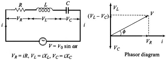
Questions

5 Marks Questions

Take a timed test

43 questions · self-marked practice — reveal the answer and mark yourself.

Question 15 Marks
A small town with a demand of 800kW of electric power at 220V is situated 15km away from an electric plant generating power at 440V. The resistance of the two wire line carrying power is 0.5Ω per km. The town gets power from the line through a 4000-220V step-down transformer at a sub-station in the town.
  1. Estimate the line power loss in the form of heat.
  2. How much power must the plant supply, assuming there is negligible power loss due to leakage?
  3. Characterise the step up transformer at the plant.
Answer
Total electric power required, $P = 800kW = 800 × 103w$
Supply voltage, $V = 220V$
Voltage at which electric plant is generating power, $V = 440V$
Distance between the town and power generating station, $d = 15\  km,$
Resistance of the two wire lines carrying power $= 0.5\Omega/\text{km}$
Total resistance of the wires, $\text{R} = (15 + 15)0.5 = 15\Omega$
A step-down transformer of rating 4000 - 220V is used in the sub-station.
Input voltage, $V_1 = 4000V$
Output voltage, $V_2 = 220V$
Rms current in the wire lines is given as:
$\text{I}=\frac{\text{P}}{\text{V}_1}$
$=\frac{800\times10^3}{4000}=200\text{A}$
  1. Line power loss $= I^2R$
$= (200)^2 \times 15$
$= 600 \times 10^3W$
$= 600kW$
  1. Assuming that the power loss is negligible due to the leakage of the current:
    Total power supplied by the plant $= 800kW + 600kW = 1400kW$
  2. Voltage drop in the power line $= IR = 200 × 15 = 3000V$
    Hence, total voltage transmitted from the plant $= 3000 + 4000 = 7000V$
    Also, the power generated is $440v.$
    Hence, the rating of the step-up transformer situated at the power plant is $440V - 7000V.$
View full question & answer
Question 25 Marks
During a thunderstorm the ‘live' wire of the transmission line fell down on the ground. A group of boys passing through noticed it and some of them wanted to place the wire by the side. As they were approaching the wire and trying to lift it, Bari noticed it and immediately pushed them away to prevent them from touching the wire. Two of them got hunt in the process. Bari took them to a doctor to get medical aid.
Based on the above paragraph, answer the following:
  1. Write two values which Bari displayed during the incident.
  2. Why is it that a bird can sit over a suspended ‘live' wire without any harm whereas touching it on the ground can give a fatal shock?
  3. The electric power from a power plant is set up to a very high voltage before transmitting it to distant consumers. Write the reason for it.
Answer
  1. Caring, helpful, presence of mind.
  2. Current passes between two points only when there is a potential difference between them.
  3. To minimise power loss during transmission.
View full question & answer
Question 35 Marks
Hari is a student of Class X in a school near his village. His uncle gifted him a bicycle with a dynamo fitted in it. He was thrilled to find that while cycling during night, he could light the bulb and see the objects on the road clearly. He, however, did not know how this device works. He asked this question to his teacher. The teacher considered it an opportunity and explained the working of a dynamo to the whole class.
Answer the following questions:
  1. State the principle and working of a dynamo.
  2. Write two values each displayed by Hari and his Science teacher.
Answer
  1. Principle When magnetic flux through a coil changes, an emf is induced across its ends. Working: When the coil (Armature) is rotated in a uniform magnetic field by some external means, the magnetic flux through it changes. So an emf is induced across the ends of the coil connected to an external circuit by means of slip rings and brushes.
  2. Two values displayed by Hari: (Any two)
Scientific temperament/curiosity/learning attitude.

Two values displayed by Science teacher: (Any two)

Responsive/caring and concerned/encouraging.
View full question & answer
Question 45 Marks
Shiv had a high tension tower erected on his farm land. He kept complaining to the authorities to remove it since it occupied a large portion of his land. His uncle, who was a teacher, explained to him the need for erecting these towers for efficient transmission of power. As Shiv got convinced and realised significance, he stopped complaining.
Based on the above paragraph, answer the following questions:
  1. Why is it necessary to transport power at high voltages?
  2. ‘A low power factor implies large power loss'. Explain.
  3. Write the two values displayed by Shiv and his Uncle.
Answer
  1. To reduce power losses in the transmission line.
  2. Since power loss is inversely proportional to power factor.
$(\text{P} = \text{VI}\cos\varphi$ where $\cos\varphi$is power factor). To supply a given power at a given voltage, if $\cos\varphi$is small, we have to increase current accordingly. This will lead to large power loss $(\text{I}^{2}\text{R})$ in transmission/

$(\text{Effective Power} = \frac{\text{True Power }}{\cos\varphi})$
  1. Values displayed by
  1. Shiv – understanding nature/respecting elders/helping nature/caring, etc.
  2. Uncle– knowledgeable/helping nature/caring, etc.
View full question & answer
Question 55 Marks
Seema's uncle was advised by his doctor to have an MRI (Magnetic Resonance Imaging) scan of his brain. Her uncle felt it to be expensive and wanted to postpone it. When Seema learnt about this, she took the help of her family and also approached the doctor, who also offered a substantial discount. She then convinced her uncle to undergo the test to enable the doctor to know the condition of his brain. The information thus obtained greatly helped the doctor to treat him properly.
Based on the above paragraph, answer the following questions:
  1. What according to you are the values displayed by Seema, her family and the doctor?
  2. What could be the possible reason for MRI test to be so expensive?
  3. Assuming that MRI test was performed using a magnetic field of 0.1 T., find the minimum and maximum values of the force that the magnetic field could exert on a proton $($charge $= 1.6 x 10^{-19} C)$ moving with a speed of $10^4$ m/s.
Answer
  1. Value displayed by:
Seema: Helpful, considerate.
Family: Concerned, Affectionate.
Doctor: Humane nature.
  1. Expensive machinery/technique:
$\text{F} = \text{qvB}\sin\theta$
$\text{F}_{max} = \text{qvB}= 1.6\times10^{-19}\times10^{4}\times0.1$
$ = 1.6\times10^{-16}\text{N}$
$\text{F}_{min} = \text{zero} ( \text{for } \theta = 0^{0} ).$
View full question & answer
Question 65 Marks
One morning an old man walked bare-foot to replace the fuse wire in kit kat fitted with the power supply mains for his house. Suddenly he screamed and collapsed on the floor. His wife cried loudly for help. His neighbour’s son Anil heard the cries and rushed to the place with shoes on. He took a wooden baton and used it to switch off the main supply.
Answer the following questions:
  1. What is the voltage and frequency of mains supply in India?
  2. These days most of the electrical devices we use require a.c. voltage. Why?
  3. Can a transformer be used to step up d.c.voltage?
  4. Write two qualities displayed by Anil by his action.
Answer
  1. voltage = 220 V.
frequency = 50 Hz.
  1.  
  1. It can be stepped up / stepped down.
  2. It can be converted into d.c.
  3. Line losses can be minimised.
  1. No.
  2. Helping/Brave/Kind/Knowledge about AC or DC/Knowledge about insulator & conductors/Awareness about safety precautions.
View full question & answer
Question 75 Marks
Ajit had a high tension tower erected on his farm land. He kept complaining to the authorities to remove it as it was occupying a large portion of his land. His uncle, who was a teacher, explained to him the need for erecting these towers for efficient transmission of power. As Ajit realised its significance, he stopped complaining.
Answer the following questions:
  1. Why is it necessary to transport power at high voltage?
  2. A low power factor implies large power loss. Explain.
  3. Write two values each displayed by Ajit and his uncle.
Answer
  1. For the same power at high voltage, current in the transmission wires becomes smaller.
$\therefore$ power loss is less.

If power factor is less, current in the cables is more so power loss is more.

Alternate Answer

$\text{P}_{\text{av}} = \text{E}_{\text{v}}\text{I}_{\text{v}}\cos\theta$
  1. If cos ? is less, ?? is more so power loss is more.
  2. Values displayed.
By Ajit (Any two) – Social Awareness, understanding nature, concern for society.
By Uncle - Knowledgeable, professional honesty, concern for society.
View full question & answer
Question 85 Marks
A group of students while coming from the school noticed a box marked "Danger H.T. 2200 V" at a substation in the main street. They did not understand the utility of such a high voltage, while they argued, the supply was only 220 V.They asked their teacher this question the next day. The teacher thought it to be an important question and therefore explained to the whole class.
Answer the following questions:
  1. What device is used to bring the high voltage down to low voltage of a.c. Current and what is the principle of its working?
  2. Is it possible to use this device for bringing down the high d.c. Voltage to the low voltage? Explain.
  3. Write the values displayed by the students and the teacher.
Answer
  1. Transformer:
Working principle: Mutual induction Whenever an alternative voltage is applied in the primary windings, an emf is induced in the secondary windings.
  1. No, There is no induced emf for a dc voltage in the primary.
  2. Inquisitive nature/Scientific temperament. Concern for students/Helpfulness/Professional honesty.
View full question & answer
Question 95 Marks
  1. Derive an expression for the average power consumed in a series LCR circuit connected to a.c. source in which the phase difference between the voltage and the current in the circuit is $\phi$.
  2. Define the quality factor in an a.c. circuit. Why should the quality factor have high value in receiving circuits? Name the factors on which it depends.
Answer
  1. In a series LCR circuit.
Voltage $\text{v} = \text{v}_{m} \sin\omega\text{t}$
Current in the circuit is given by $\text{i} =\text{i}_{m} \sin\big(\omega\text{t} + \Phi\big)$
Therefore, the instantaneous power $p_i$ supplied by the source is $\text{p}_{i} = \text{vi} = \big(\text{V}_{m}\sin\omega\text{t}\big)\times[\text{i}_{m}\sin\big(\omega\text{t} + \phi\big)]$

$ =\frac{\text{v}_{m}\text{i}_{m}}{2}[cos\phi - cos\big(2\omega\text{t} +\phi\big)]$
The average power over a cycle is given by the average of the two terms on the R.H.S.. It is only the second term which is time-dependent. Its average over a complete cycle is zero (the positive half of the cosine cancels the negative.
$\text{P}_{av}$
$ = \text{VI} \cos \phi$
  1. Quality factor: The ratio of the voltage drop (in a series LCR circuit) across the inductor (or capacitor) to the voltage drop across resistor under resonance conditions.
Reason: Selectivity (or sharpness of resonance) of the circuit becomes large.
Factors: depends on inductance , capacitance and resistance.
View full question & answer
Question 105 Marks
The teachers of Geeta’s school took the students on a study trip to a power generating station, located nearly 200km away from the city. The teacher explained that electrical energy is transmitted over such a long distance to their city, in the form of alternating current (ac) raised to a high voltage. At the receiving end in the city, the voltage is reduced to operate the devices. As a result, the power loss is reduced. Geeta listened to the teacher and asked questions about how the ac is converted to a higher or lower voltage.
  1. Name the device used to change the alternating voltage to a higher or lower value. State one cause for power dissipation in this device.
  2. Explain with an example, how power loss is reduced if the energy is transmitted over long distances as an alternating current rather than a direct current.
  3. Write two values each shown by the teachers and Geeta.
Answer
  1. Transformer
Copper Loss: Energy is lost in the formof heat energy due to flow of current in the copper windings of transformer because of its resistance. This loss is called copper loss.
  1. For long distances, alternating current of high voltage is used because current reduces siginificatly and power loss due to heating $(I^2R)$ also reduces significantly.
Example: Electric power from power station is transferred to substation in 44kV a.c., and then it is reduced to 22kV a.c.
  1. Values shown by teachers good demonstrator, caring Values shown by Geeta Good listener, curious.
View full question & answer
Question 115 Marks
How does the sign of the phase angle $\phi$, by which the supply voltage leads the current in an LCR series circuit, change as the supply frequency is gradually increased from very low to very high values.
Answer

Series LCR-Circuit

We know that the phase angle $(\phi)$ by which voltage leads the current in R-L-C series circuit is given by
$\tan\phi=\frac{\text{X}_\text{L}-\text{X}_\text{C}}{\text{R}}=\frac{\omega-\frac{1}{\omega\text{C}}}{\text{R}}$
Ae small frequencies, $X_L < X_C$
tan is negative, i.e., $\tan\phi<0(\text{for v}<\text{v}_0)$
At resonant frequency, $X_L = X_C,$
$\therefore\ \tan\phi=0\Big(\text{for v}=\text{v}_0=\frac{1}{2\pi\sqrt{2\text{C}}}\Big)$.
View full question & answer
Question 125 Marks
A 60W load is connected to the secondary of a transformer whose primary draws line voltage. If a current of 0.54A flows in the load, what is the current in the primary coil? Comment on the type of transformer being used.
Answer
According to the problem, $P_s = 60W, I_s = 0.54A$
Let $V_S, I_S$ and $V_P, I_P$ are voltages and current of the secondary and primary of the transtormer respectively.
Taking primary voltage as 220V.
$\Rightarrow P_S = 60W, I_S = 0.54A$
$\Rightarrow\ \text{V}_\text{S}=\frac{60}{0.54}=110\text{V}$
Voltage in the secondary $(E_S)$ is lee than Vpltage in the primary $(E_P).$
Therefore, the transformer is step down transformer.
Since, the transformation ratio
$\text{r}=\frac{\text{V}_\text{s}}{\text{V}_\text{p}}=\frac{\text{I}_\text{p}}{\text{I}_\text{s}}$
Substituting the values, $\frac{110\text{V}}{220\text{V}}=\frac{\text{I}_\text{p}}{0.54\text{A}}$
On solving $\text{I}_\text{p}=0.27\text{A}$
View full question & answer
Question 135 Marks
A coil of 0.01 henry inductance and 1ohm resistance is connected to 200volt, 50Hz ac supply. Find the impedance of the circuit and time lag between max. alternating voltage and current.
Answer
$\text{X}_\text{L}=\omega\text{L}=2\pi\text{fL}=3.14\Omega\sqrt{\text{b}^2-4\text{ac}}$
$\text{Z}=\sqrt{\text{R}^2+\text{L}^2}=\sqrt{(3.14)^2+(1)^2}=\sqrt{10.86}=3.3\Omega$
$\tan\phi=\frac{\omega\text{L}}{\text{R}}=3.14$
$\Rightarrow\ \phi=\tan^(-1)(3.14)=72^\circ=\frac{72\times\pi}{180}\text{radiam}$
Timelag, $\Delta\text{t}=\frac{\phi}{\omega}=\frac{72\times\pi}{180\times2\pi\times50}=\frac{1}{150}\text{s}$
View full question & answer
Question 145 Marks
A resistor of resistance $100\Omega$ is connected to an AC source $\in=(12\text{V})\sin(250\pi\text{s}^{-1})\text{t}.$ Find the energy dissipated as heat during $\text{t}=0$ to $\text{t}=1.0\text{ms}.$
Answer
$\text{H}=\frac{\text{V}^2}{\text{R}}\text{T},\ \text{E}_0=12\text{V},\ \omega=250\pi,\ \text{R}=100\Omega$
$\text{H}=\int\limits_0^\text{H}=\int\frac{\text{E}_0\sin^2\omega\text{t}}{\text{R}}\text{dt}$
$=\frac{144}{100}\int\sin^2\omega\text{t}\text{ dt}=1.44\int\Big(\frac{1-\cos2\omega\text{t}}{2}\Big)\text{dt}$
$=\frac{1.44}{2}\Big[\int\limits_0^{10^{-3}}\text{dt}-\int\limits_0^{10^{-3}}\cos2\omega\text{t}\text{ dt}$
$=0.72\Bigg[10^{-3}-\Big(\frac{\sin2\omega\text{t}}{2\omega}\Big)_0^{10^{-3}}\Bigg]$
$=0.72\Big[\frac{1}{1000}-\frac{1}{500\pi}\Big]$
$=\frac{(\pi-2)}{1000\pi}\times0.72=0.0002614$
$=2.61\times10^{-4}{\text{J}}$
View full question & answer
Question 155 Marks
A capacitor of capacitance $10\mu\text{F}$ is connected to an oscillator with output voltage $\in=(10\text{V})\sin\omega\text{t}.$ Find the peak currents in the circuit for $\omega=10\text{s}^{-1},100\text{s}^{-1},500\text{s}^{-1},1000\text{s}^{-1}.$
Answer
$\text{C}=10\mu\text{F}=10\times10^{-6}\text{F}=10^{-5}\text{F}$
$\text{E}=(10\text{V})=\sin\omega\text{t}$
  1. $\text{I}=\frac{\text{E}_0}{\text{X}_\text{C}}=\frac{\text{E}_0}{\Big(\frac{1}{\omega\text{C}}\Big)}$
$=\frac{10}{\Big(\frac{1}{10\times10^{-5}}\Big)}=1\times10^{-3}\text{A}$
  1. $\omega=100\text{s}^{-1}$
$\text{I}=\frac{\text{E}_0}{\Big(\frac{1}{\omega\text{C}}\Big)}$

$=\frac{10}{\Big(\frac{1}{100\times10^{-5}}\Big)}=1\times10^{-2}\text{A}=0.01\text{A}$
  1. $\omega=500\text{s}^{-1}$
$\text{I}=\frac{\text{E}_0}{\Big(\frac{1}{\omega\text{C}}\Big)}$

$=\frac{10}{\Big(\frac{1}{500\times10^{-5}}\Big)}=5\times10^{-2}\text{A}=0.05\text{A}$
  1. $\omega=1000\text{s}^{-1}$
$\text{I}=\frac{\text{E}_0}{\Big(\frac{1}{\omega\text{C}}\Big)}$

$=\frac{10}{\Big(\frac{1}{1000\times10^{-5}}\Big)}=1\times10^{-1}\text{A}=0.1\text{A}$
View full question & answer
Question 165 Marks
A coil has a resistance of $10\Omega$ and an inductance of 0.4 henry. It is connected to an AC source of $6.5\text{V},\frac{30}{\pi}\ \text{Hz}$ Find the average power consumed in the circuit.
Answer
$\text{R}=10\Omega,\text{L}=0.4\text{ henry}$
$\text{E}=6.5\text{V},\text{f}=\frac{30}{\pi}\text{Hz}$
$\text{Z}=\sqrt{\text{R}^2+{\text{X}_\text{L}}^{2}}=\sqrt{\text{R}^2+(2\pi\text{fL})^2}$
$\text{Power}=\text{V}_\text{rms}\text{I}_\text{rms}\cos\phi$
$=6.5\times\frac{6.5}{\text{Z}}\times\frac{\text{R}}{\text{Z}}$
$=\frac{6.5\times6.5\times10}{\Big[\sqrt{\text{R}^2+(2\pi\text{f})^2}\Big]}$
$=\frac{6.5\times6.5\times10}{10^2+\Big(2\pi\times\frac{30}{\pi}\times0.4\Big)^2}$
$=\frac{6.5\times6.5\times10}{100+576}=0.625=\frac{5}{8}\omega$
View full question & answer
Question 175 Marks
Do the same exercise as above with the replacement of the earlier transformer by a 40, 000-220V step-down transformer (Neglect, as before, leakage losses though this may not be a good assumption any longer because of the very high voltage transmission involved). Hence, explain why high voltage transmission is preferred?
Answer
The rating of a step-down transformer is $40000V-220V.$
Input voltage, $V_1 = 40000V$
Output voltage, $V_2 = 220V$
Total electric power required, $P = 800kW = 800 \times 10^3W$
Source potential,$ V = 220V$
Voltage at which the electric plant generates power, $V' = 440V$
Resistance of the two wire lines carrvrnq power $=0.5\Omega/\text{km}$
Total resistance of the wire lines, $\text{R}=(15+15)0.5=15\Omega$
$P = V_1I$
Rms current in the wire line is given as:
$\text{I}=\frac{\text{P}}{\text{V}_1}$
$=\frac{800\times10^3}{40000}=20\text{A}$
  1. Line power loss $= I^2R$
$= (20)^2 \times 15$
$= 6kW$
  1. Assuming that the power loss is negligible due to the leakage of current,
    Hence, power supplied by the plant = 800kW + 6kW = 806kW
  2. Voltage drop in the power line = IR = 20 × 15 = 30V
Hence, voltage that is transmltted by the power plant = 300 + 40000 = 40300V
The power is being generated in the plant at 440V.
Hence, the rating of the step-up transformer needed at the plant is 440V - 40300V.
Hence, power loss during transmission $=\frac{600}{1400}\times100=42.8\%$
In the previous exercise, the power loss due to the same reason is $=\frac{600}{806}\times100=0.744\%$
Since the power loss is less for a high voltage transrnlsston, high voltage transmissions are preferred for this purpose.
View full question & answer
Question 185 Marks
A 100μF capacitor in series with a 40Ω resistance is connected to a 110V, 60Hz supply.
  1. What is the maximum current in the circuit?
  2. What is the time lag between the current maximum and the voltage maximum?
Answer
Here given,
Capacitance,
$C = 100\mu F = 100 \times 10^{-6}F$
$= 10^{-4}F$
Resistance, $\text{R}=40\Omega$
Rms voltage, $E_v = 110$ volt
Peak voltage, $\text{E}_0=\sqrt{2}.\text{E}_{\text{v}}=\sqrt{2}\times110\text{V}$
Frequency of Ac supply, v = 60Hz.,
$\therefore\ \omega=2\pi\text{v}=120\pi\text{ rad/s}$
Peak current,$ I_0 = ?$
  1. In RC circuit, as
$\text{Z}=\sqrt{\text{R}^2+\text{X}_{\text{c}}^{2}}=\sqrt{\text{R}^2+\frac{1}{\omega^2\text{C}^2}}$
Therefore,
$\text{I}_0=\frac{\text{E}_0}{\sqrt{\text{R}^2+\frac{1}{\omega^2\text{C}^2}}}$
$=\frac{\sqrt{2}\times110}{\sqrt{1600+\frac{1}{(120\pi\times10^{-4})^2}}}$
$I_0 = 3.24$ amp.
  1. In RC circuit, voltage lags behind the current by phase angle $\phi,$
where $\phi$ is given by,
$\tan\phi=\frac{1/\omega\text{C}}{\text{R}}$

$=\frac{1}{\omega\text{CR}}$
$=\frac{1}{120\pi\times10^{-4}\times40}$
$= 0.6628$
$\Rightarrow\ \phi=\tan^{-1}(0.6628)=33.5^{\circ}$
$=\frac{33.5\pi}{180}\text{rad}.$
Hence,
$\text{Time lag}=\frac{\phi}{\omega}$
$=\frac{33.5\pi}{180\times120\pi}$
$= 1.55 \times 10^{-3}$sec.
View full question & answer
Question 195 Marks
A circuit containing a 80 mH inductor and a 60 μF capacitor in series is connected to a 230V, 50Hz supply. The resistance of the circuit is negligible.
  1. Obtain the current amplitude and rms values.
  2. Obtain the rms values of potential drops across each element.
  3. What is the average power transferred to the inductor?
  4. What is the average power transferred to the capacitor?
  5. What is the total average power absorbed by the circuit? ['Average' implies 'averaged over one cycle'.]
Answer
Here,
Inductance, $L = 80 mH = 80 \times 10^{-3}H$
Capacitance, $C = 60 \mu F = 60 \times 10^{-6}F$
Resistance, $R = 0$
RMS voltage, $E_v = 230\  V$
Peak voltage, $\text{E}_0=\sqrt{2}\times\text{E}_{\text{v}}$
$=\sqrt{2}\times230\text{V}$
Frequency of Ac supply, f = 50Hz
$\therefore\ \omega=2\pi\text{f}$
$=100\pi\text{ rad/s}$
  1. We have to find $I_0 = ?, I_v = ?$
Therefore,
$\text{I}_0=\frac{\text{E}_0}{\Big(\omega\text{L}-\frac{1}{\omega\text{L}}\Big)}$
$=\frac{230\sqrt{2}}{\Big(100\pi\times80\times10^{-3}-\frac{1}{100\pi\times60\times10^{-6}}\Big)}$
$=\frac{230\sqrt{2}}{\Big(8\pi-\frac{1000}{6\pi}\Big)}$
$=\frac{230\sqrt{2}}{-27.91}$
= -11.63amp.
and,
$\text{I}_{\text{v}}=\frac{\text{I}_0}{\sqrt{2}}=\frac{-11.63}{1.414}=-8.23amp.$
Negative sign appears as $\omega<\frac{1}{\omega\text{C}}.$
$\therefore$ e.m.f lags behind the current by 90º
  1. Rms value of potential drop across L,
$\text{V}=\text{I}_{\text{v}}\times\omega\text{L}$
$=8.23\times100\pi\times80\times10^{-3}$
= 206.74volt.
Rms value of potential drop across C,
$\text{V}=\text{I}_{\text{v}}\times\frac{1}{\omega\text{C}}$
$=8.23\times\frac{1}{100\pi\times60\times10^{-6}}$
= 436.84volt.
As voltages across L and C are 180º out of phase, therefore, they get subtracted.
That is why applied r.m.s. voltage= 436.84 - 206.74 = 230.1volt.
  1. Average power transferred over a complete cycle by the source to inductor is always zero because of phase difference of $\frac{\pi}{2}$ between voltage and current through the inductor.
  2. Average power transferred over a complete cycle by the source to the capacitor is also zero because of phase difference of $\frac{\pi}{2}$ between voltage and current through capacitor.
  3. Total average power absorbed by the circuit is also, therefore zero.
View full question & answer
Question 205 Marks
Keeping the source frequency equal to the resonating frequency of the series LCR circuit, if the three elements, L, C and R are arranged in parallel, show that the total current in the parallel LCR circuit is minimum at this frequency. Obtain the current rms value in each branch of the circuit for the elements and source specified in Exercise 7.11 for this frequency.
Answer
Given, an LCR circuit. L, C and Rare arranged in parallel and the source frequency is kept equal to the resonating frequency.
Then,
Using the formula for resonant frequency,
$\omega_{\text{r}}=\frac{1}{\sqrt{\text{LC}}}$
$=\frac{1}{\sqrt{5\times80\times10^{-6}}}$
$=\frac{1}{\sqrt{400\times10^{-6}}}$
= 50rad $s^{-1}$
Since elements are in parallel, reactance X of L and C in parallel is given by
$\frac{1}{\text{X}}=\frac{1}{\omega\text{L}}=\frac{1}{1/\omega\text{C}}=\frac{1}{\omega\text{L}}-\omega\text{C}$
Impedance of R and X in parallel is given by
$\frac{1}{\text{Z}}=\sqrt{\frac{1}{\text{R}^2}+\frac{1}{\text{X}^2}}=\sqrt{\frac{1}{\text{R}^2}+\Big(\frac{1}{\omega\text{L}}-\omega\text{C}\Big)^2}$
$\frac{1}{\text{Z}}=\sqrt{\frac{1+\text{R}^2\Big(\frac{1}{\omega\text{L}}-\omega\text{C}\Big)^2}{\text{R}}}$
$\text{Z}=\frac{\text{R}}{\sqrt{\Big[1+\text{R}^2\Big(\frac{1}{\omega\text{L}}-\omega\text{C}\Big)^2\Big]}}$
which is less than resistance R.
At resonant frequency,
$\omega\text{L}=\frac{1}{\omega\text{C}}\ \text{or}\ \omega\text{C}=\frac{1}{\omega\text{L}}$
$\text{and }\Big(\frac{1}{\omega\text{L}-\omega\text{C}}\Big)=0$
Then, impedance Z = Rand will be maximum.
Hence, current will be minimum at resonant frequency in the parallel LCR circuit.
From Ex. 11:
Inductance, L = 5H
Capacitance, $C = 80 \times 10^{-6}F$
Resistnace, $\text{R}=40\Omega$
$E_{rms} = 230V.$
Therfore,
$(\text{I}_{\text{R}})_{\text{rms}}=\frac{\text{V}_{\text{rms}}}{\text{R}}=\frac{230}{40}=5.75\text{A}.$
$(\text{I}_{\text{L}})_{\text{rms}}=\frac{\text{V}_{\text{rms}}}{\omega\text{L}}=\frac{230}{50\times5}=0.92\text{A}.$
$(\text{I}_{\text{C}})_{\text{rms}}=\frac{\text{V}_{\text{rms}}}{1/\omega\text{C}}={230}\times{50}\times80\times10^{-6}=0.92\text{A}.$
Current through Land C will be in opposite phase. Hence, current in circuit will be only $5.75\Big(=\frac{\text{V}_{\text{rms}}}{\text{R}}\Big)$ as, circuit impedance will be equal to R only.
View full question & answer
Question 215 Marks
1MW power is to be delivered from a power station to a town 10km away. One uses a pair of Cu wires of radius 0.5cm for this purpose. Calculate the fraction of ohmic losses to power transmitted if,
  1. Power is transmitted at 220V. Comment on the feasibility of doing this.
  2. A step-up transformer is used to boost the voltage to 11000V, power transmitted, then a step-down transfomer is used to bring voltage to 220V.
$(\rho_\text{Cu}1.7\times10^{-8}\text{SI unit})$.
Answer
  1. The power station is 10km away from the town.
Length of pair of CU wires used, L = 20km = 20000m.
Resistance of Cu wires, $\text{R}=\rho_\text{cu}\frac{\text{L}}{\text{A}}=\rho\frac{\text{L}}{\pi\text{r}^2}$
$=\frac{1.7\times10^{-8}\times2\times10^{4}}{\pi(0.5\times10^{-2})^2}=4\Omega$
I at 220V. VI $10^6$ W; $\text{I}=\frac{10^6}{220}=0.45\times10^4\text{A}$
$RI^2 =$ Power loss
$= 4 \times (0.45)^2 \times 10^8W$
$> 10^6W$
Power losses are very large, hence, this method is not suitable for transmission.
  1. When Power $P = 10^6$ W is transmitted ar 11000V.
$V'I' = 10^6 W = 11000V.$
Current drawn, $\text{I}'=\frac{1}{1.1}\times10^2$
Power loss $=\text{I}^2\text{R}=\frac{1}{1.21}\times4\times10^4$
$3.3\times10^4\text{W}$
Fraction of power loss $=\frac{\Delta\text{P}}{\text{P}}=\frac{3.3\times10^4}{10^6}=3.3\%$
View full question & answer
Question 225 Marks
An electric bulb is designed to consume 55W when operated at 110 volts. It is connected to a 220V, 50Hz line through a choke coil in series. What should be the inductance of the coil for which the bulb gets correct voltage?
Answer

Power = 55W, Voltage = 110V
Resistance $=\frac{\text{V}^2}{\text{P}}=\frac{110\times110}{55}=220\Omega$
frequency $(\text{f})=50\text{Hz}$
Current in the circuit $=\frac{\text{V}}{\text{Z}}=\frac{\text{V}}{\sqrt{\text{R}^2+(\omega\text{L})^2}}$
Voltage drop across the resistor $=\text{ir}=\frac{\text{VR}}{\sqrt{\text{R}^2+(\omega\text{L})^2}}$
$=\frac{220\times220}{\sqrt{(220)^2+(100\pi\text{L})^2}}=110$
$\Rightarrow\ 220\times2=\sqrt{(220)^2+(100\pi\text{L})^2}$
$\Rightarrow\ (220)^2+(100\pi\text{L})^2=(440)^2$
$\Rightarrow\ 48400+10^4\pi^2\text{L}^2=193600$
$\Rightarrow\ 10^4\pi^2\text{L}^2=193600-48400$
$\Rightarrow\ \text{L}^2=\frac{142500}{\pi^2\times10^4}=1.4726$
$\Rightarrow\ \text{L}=1.2135\approx1.2\text{Hz}$
View full question & answer
Question 235 Marks
A coil of inductance 0.50H and resistance 100Ω is connected to a 240V, 50Hz ac supply.
  1. What is the maximum current in the coil?
  2. What is the time lag between the voltage maximum and the current maximum?
Answer
Given,
Inductance, $L = 0.50H$
Resistance, $\text{R}=100\Omega$
Effective voltage, $E_v = 240V$
Frequency of the ac supply, $f = 50Hz$
We can calculate,
Angular frequency, $\omega=2\pi\text{f}=100\pi$
Peak voltage, $\text{E}_0=\sqrt{2}\text{E}_{\text{v}}=\sqrt{2}\times240\text{V}$
  1. Maximum amount of current in the coil is given by,
$\text{I}_0=\frac{\text{E}_0}{\sqrt{\text{R}^2+\omega^2\text{L}^2}}$
$\text{I}_0=\frac{\sqrt{2}\times240}{\sqrt{10^4+(100\pi\times0.5)^2}}$
$= 1.82A.$
  1. In LR circuit,
$\text{If},\ \text{E}=\text{E}_0\cos\omega\text{t}\ \text{then},\ \text{I}=\text{I}_0\cos(\omega\text{t}-\phi)$
Now,
At $t = 0, E = E_0$ i.e., voltage is maximum.
$\text{At}\ \ \ \text{t}=\frac{\phi}{\omega},\ \text{I}=\text{I}_0\cos(\phi-\phi)=\text{I}_0\times1,$current is maximum
$\therefore$ Time lag between voltage maximum and current maximum $=\frac{\phi}{\omega}$
Using the below given relation, we can find the value of $\phi.$
$\tan\phi=\frac{\omega\text{L}}{\text{R}}$
$=\frac{2\pi\times50\times0.50}{100}$
$=\frac{22}{7\times2}$
$= 1.571$
$\Rightarrow\ \phi=\tan^{-1}(1.571)$
$= 57.5º$
$=\frac{57.5\pi}{180}\text{radian}$
Thus,
$\text{Time lag}=\frac{\phi}{\omega}$
$=\frac{57.5\pi}{180\times2\pi\text{f}}$
$=\frac{57.5}{180\times2\times50}$
$= 3.19 \times 10^{-3}s.$
is the required time lag between the maximum voltage and maximum current.
View full question & answer
Question 245 Marks
A device 'X' is connected to an a.c source. The variation of voltage, current and power in one complete cycle is shown in Fig.
  1. Which curve shows power consumption over a full cycle?
  2. What is the average power consumption over a cycle?
  3. Identify the device 'X'.
Answer
  1. Power is the product of voltage and current (Power = P = VI).
So, the curve of power will be having maximum amplitude, equals to the product of amplitudes of voltage (V) and current (I) curve. Frequencies , of B and C are-equal, therefore they represent V and I curves. So, the curve A represents power.
  1. The full cycle of the graph (as shown by shaded area in the diagram) consists of one positive and one negative symmetrical area.


Hence, average power consumption over a cycle is zero.
  1. Here phase difference between V and I is $\frac{\pi}{2}$ therefore, the device 'X' may be an inductor (L) or capacitor (C) or the series combination of L and C.
View full question & answer
Question 255 Marks
Figure shows a series LCR circuit connected to a variable frequency 230V source. L = 5.0H, C = 80μF, R = 40Ω.
  1. Determine the source frequency which drives the circuit in resonance
  2. Obtain the impedance of the circuit and the amplitude of current at the resonating frequency.
  3. Determine the rms potential drops across the three elements of the circuit. Show that the potential drop across the LC combination is zero at the resonating frequency.
Answer
Here, we are given a LCR circuit.
Inductance, $L = 5.0H$
Resistance, $\text{R}=40\Omega$
Capacitance, $C = 80\mu F = 80 \times 10^{-6}F$
Effective voltage, $E_v = 230$volt
$\Rightarrow\ \text{Peak voltage},\ \text{E}_0=\sqrt{2}\text{E}_{\text{v}}=\sqrt{2}\times230\text{V}$
  1. Resonance angular frequency is given by
$\omega_{\text{r}}=\frac{1}{\sqrt{\text{LC}}}$
$=\frac{1}{\sqrt{5\times80\times10^{-6}}}$
$=\frac{1}{2\times10^{-2}}$
= 50rad/sec.
  1. Impedance of the circuit,
$\text{Z}=\sqrt{\text{R}^2+\big(\omega\text{L}-\frac{1}{\omega\text{C}}\big)^2}$
At resonance, $\omega\text{L}=\frac{1}{\omega\text{C}}$
Therefore,
$\text{Z}=\sqrt{\text{R}^2}=\text{R}=40\Omega$
Amplitude of current at resonating frequency
Peak value of current, $\text{I}_0=\frac{\text{E}_0}{\text{z}}=\frac{\sqrt{2}\times230}{40}=8.13\text{A}$
Rms value of current, $\text{I}_{\text{v}}=\frac{\text{I}_0}{\sqrt{2}}=\frac{8.13}{\sqrt{2}}=5.75\text{A}$
  1. Potential drop across L
$\text{V}_{\text{L rms}}=\text{I}_\text{v}\omega_{\text{r}}\text{L}$
$= 5.75 × 50 × 5.0$
$= 1437.5V$
Potential drop across R
$\mathrm{V_{R\ rms} = I_v \times\ R}$
$= 5.75 × 40$
$= 230$volts
Potential drop across C
$\text{V}_{\text{C rms}}=\text{I}_{\text{v}}\Big(\frac{1}{\omega_{\text{r}}\text{C}}\Big)$
$=5.75\times\frac{1}{50\times80\times10^{-6}}$
$=\frac{5.75}{4}\times10^3$
= 1437.5V
Therefore,
Potential drop across LC circuit
$\mathrm{V_{LC\  rms} = V_{L\ rms} - V_{C\ rms} = 0}$
Thus, the potential drop across the LC combination is zero at the resonating frequency.
View full question & answer
Question 265 Marks
A series LCR circuit with L = 0.12H, C = 480nF, R = 23Ω is connected to a 230V variable frequency supply.
  1. What is the source frequency for which current amplitude is maximum. Obtain this maximum value.
  2. What is the source frequency for which average power absorbed by the circuit is maximum. Obtain the value of this maximum power.
  3. For which frequencies of the source is the power transferred to the circuit half the power at resonant frequency? What is the current amplitude at these frequencies?
  4. What is the Q-factor of the given circuit?
Answer
  1. Here,
Inductance, L = 0.12H
Resistance, $\text{R}=23\Omega$
Capacitance, $C = 480nF = 480 \times 10^{-9}F$
Rms voltage, $E_v = 230$volt
Peak voltage, $\text{E}_0=\sqrt{2}\text{E}_{\text{v}}=\sqrt{2}\times230\text{volt}.$
$\text{Maximum current},\ \text{I}_0=\frac{\text{E}_0}{\sqrt{\text{R}^2+\Big(\omega\text{L}-\frac{1}{\omega\text{C}}\Big)^2}}$
$I_0$ would be maximum, when
$\omega_{\text{r}}=\omega=\frac{1}{\sqrt{\text{LC}}}$
$=\frac{1}{\sqrt{0.12\times480\times10^{-9}}}$
$= 4166.7$rad $s^{-1}$
$\Rightarrow\ \text{I}_0=\frac{\text{E}_0}{\text{R}}$
$=\frac{\sqrt{2}\times230}{23}=14.14\text{amp}.$
  1. Average power absorbed by the circuit is maximum, when $I= I_0$
$\text{P}_{\text{av}}=\frac{1}{2}\text{I}_{0}^{2}\text{R}$
$=\frac{1}{2}(14.14)^2\times23$
= 2299.3watt
  1. The two angular frequencies for which the power transferred to the circuit is half the power at the resonant frequency,
$\omega=\omega_{\text{r}}\pm\Delta\omega$
When,
$\Delta\omega=\frac{\text{R}}{2\text{L}}$
$=\frac{23}{2\times0.12}=95.83\text{rad }\text{s}^{-1}$
$\therefore$ angular frequencies at which power transferred is half $=\omega_{\text{r}}\pm\Delta\omega$'
$=4166.7\pm95.83=4262.3\ \text{and}\ 4070.87\text{rad }\text{s}^{-1}$
Current amplitude at these frequencies is
$\frac{\text{I}_0}{\sqrt{2}}=\frac{14.14}{1.414}=10\text{A}.$
  1. $\text{Q}-\text{factor}=\frac{\omega_{\text{r}}\text{L}}{\text{R}}=\frac{4166.7\times0.12}{23}=21.74.$
View full question & answer
Question 275 Marks
An LC circuit contains a 20mH inductor and a 50μF capacitor with an initial charge of 10mC. The resistance of the circuit is negligible.
Let the instant the circuit is closed be t = 0.
  1. What is the total energy stored initially? Is it conserved during LC oscillations?
  2. What is the natural frequency of the circuit?
  3. At what time is the energy stored
  1. completely electrical (i.e., stored in the capacitor)?
  2. completely magnetic (i.e., stored in the inductor)?
  1. At what times is the total energy shared equally between the inductor and the capacitor?
  2. If a resistor is inserted in the circuit, how much energy is eventually dissipated as heat?
Answer
Given, an LC circuit.
Inductance, $L = 20mH = 20 \times 10^{-3}H$
Capacitance, $C = 50\mu F = 50 \times 10^{-6}F$
Initial charge, $Q = 10mC= 10 \times 10^{-3}C$
  1. Total initial energy stored in the circuit,
$\text{E}=\frac{\text{Q}_0^2}{2\text{C}}=\frac{\big(10\times10^{-3}\big)^2}{2\times50\times10^{-6}}\text{J}=1\text{J}$
This energy stored shall remain conserved in the absence of resistance.
  1. Angular frequency,
$\omega=\frac{1}{\sqrt{\text{LC}}}$
$=\frac{1}{(20\times10^{-3}\times50\times10^{-6})^{1/2}}\text{Hz}$
$= 10^3$rad$ s^{-1}$
$\text{v}=\frac{10^3}{2\pi}\text{Hz}=159\text{Hz}.$
  1. Let, at any instant the energy stored in the circuit is completely the electrical charge on the capacitor,
  1. $\text{Q}=\text{Q}_0\cos\omega\text{t}$
then,
$\text{Q}=\text{Q}_0\cos\frac{2\pi}{\text{T}}\text{t}$
$\text{where},\ \text{T}=\frac{1}{\text{v}}=\frac{1}{159}\text{s}=6.3\text{ms}$
$\therefore$ Q is maximum only when,
$\cos\frac{2\pi}{\text{t}}=\pm1=\cos\text{n}\pi=\frac{\text{nT}}{2}$
where, n 1, 2, 3, .... ......(1)
Hence,
Energy stored is completely electrical at t = 0, T/2, T, 3T/2,.. and so on.
  1. Now, let the energy stored be completely magnetic at any instant when electrical charge = 0
i.e., q = 0.
From equation (1)
$\cos\frac{2\pi}{\text{t}}=0=\frac{\text{n}\pi}{2}$
$\text{or t}=\frac{\text{nT}}{4}$
where, n =1, 2, 3, ...
Thus, energy stored is completely magnetic at
$\text{t}=\frac{\text{T}}{4},\ \frac{3\text{T}}{4},\ \frac{5\text{T}}{4},\ .....$
  1. Energy shared between inductor and the capacitor is equal means the energy
shared is half times the maximum energy of the circuit.
$\therefore\ \text{Electrical energy}=\frac{\text{Q}^2}{2\text{C}}=\frac{1}{2}\frac{\text{Q}_0^2}{2\text{C}},$ which is half of the total energy.
This implies $\text{Q}=\frac{\text{Q}_0}{\sqrt{2}}$
Using equation (1) we have,
$\frac{\text{Q}_0}{\sqrt{2}}=\text{Q}_0.\cos\frac{2\pi}{\text{T}}\text{t}$
$\frac{1}{\sqrt{2}}=\cos\frac{2\pi}{\text{T}}\text{t}$
$\text{i.e.},\ \cos\frac{(2\text{n}+1)\pi}{4}=\cos\frac{2\pi}{\text{T}}\text{t}$
$\frac{(2\text{n}+1)\pi}{4}=\frac{2\pi}{\text{T}}\text{t}$
$\text{t}=\frac{\text{T}}{8}(2\text{n}+1);\ \ \ \text{n}=1,\ 2,\ 3,\ .....$
$\therefore\ \text{t}=\frac{\text{T}}{8},\ \frac{3\text{T}}{8},\ \frac{5\text{T}}{8},\ .....$
During these values oft, total energy will be shared equally between the inductor and the capacitor.
  1. Resistor damps out the LC oscillations. The whole of the initial energy 1.0J, is eventually dissipated as heat.
View full question & answer
Question 285 Marks
An electrical device draws 2kW power from AC mains $(\text{voltage }223\text{V}\text{(rms)}=\sqrt{50.000}\text{V})$. The current differs (lags) in phase by $\phi\Big(\tan\phi=\frac{-3}{4}\Big)$ as compared to voltage. Find,
  1. R,
  2. $X_C - X_L,$
  3. $I_M$. Another device has twice the values for $R, X_C$ and $X_L$. How are the answers affected?
Answer
Power $\text{P}=\frac{\text{V}^2}{\text{Z}}$Given, P = 2kW = 2000W,$ V_{rms} = V = 223V$
$\text{Z}=\frac{\text{V}^2}{\text{P}}=\frac{223\times223}{2\times10^3}=25$
Now, impedance $\text{Z}=25\Omega$
Impedance $\text{Z}=\sqrt{\text{R}^2+(\text{X}_\text{C}-\text{X}_\text{L})^2}$
$\Rightarrow\ \sqrt{\text{R}^2+(\text{X}_\text{C}-\text{X}_\text{L})^2}=25$
$\Rightarrow\ \text{R}^2+(\text{X}_\text{C}-\text{X}_\text{L})^2=625$
As, $\tan\phi=\frac{\text{X}_\text{C}-\text{X}_\text{L}}{\text{R}}=-\frac{3}{4}$
$\therefore\ 625=\text{R}^2+\Big(-\frac{3}{4}\text{R}\Big)^2=\frac{25}{16}$
$\text{R}^2=400$
$\Rightarrow\ \text{R}=20\Omega$
  1. Resistance $\text{R}=200\Omega.$
  2. $\text{X}_\text{L}-\text{X}_\text{C}=\frac{3\text{R}}{4}=\frac{3}{4}\times20=15\Omega.$
  3. Main current $\text{I}_\text{M}=\text{I}\sqrt{2}=\frac{\text{V}}{\text{Z}}\sqrt{2}=\frac{223}{25}\times\sqrt{2}=12.6\text{A}$.
View full question & answer
Question 295 Marks
Obtain the answers to (a) and (b) in Exercise 7.15 if the circuit is connected to a 110V, 12kHz supply? Hence, explain the statement that a capacitor is a conductor at very high frequencies. Compare this behaviour with that of a capacitor in a dc circuit after the steady state.
Answer
  1. Here,
Effective volatge, E = 110V

Frequency of Ac supply, f = 12KHz

For the high frequency,

$\omega=2\pi\text{f}=2\pi\times12\times10^3\text{rad }\text{s}^{-1}.$

$\therefore\ \text{Maximum current},\ \text{I}_0=\frac{\text{E}_0}{\sqrt{\text{R}^2+\frac{1}{\omega^2\text{c}^2}}}=\frac{2\text{E}_{\text{v}}}{\sqrt{\text{R}^2+\frac{1}{\omega^2\text{c}^2}}}$

$\Rightarrow\ \text{I}_0=\frac{\sqrt{2}\times110}{\sqrt{1600+\frac{1}{4\pi^2\times144\times10^6\times10^{-8}}}}\text{A}$

$=\frac{1.414\times110}{\sqrt{1600+0.0176}}\text{A}$

$=\frac{1.414}{40}\text{A}$

= 3.9A

[It may be noted that the capacitor term is negligible at higher frequencies.]
  1. Now, phase lag
$\tan\phi=\frac{1}{\omega\text{CR}}$

$=\frac{1}{2\pi\times12\times10^3\times10^{-4}\times40}$

$=\frac{1}{96\pi}$

i.e., we can see that, $\phi$ is nearly zero at high frequency.

It is clear from here that at high frequency, capacitor acts like a conductor.

For a D.C. circuit, after steady state has been reached, $\omega=0.$

Hence, $\chi\text{c}=\frac{1}{\omega\text{C}}=\infty$

Therefore, capacitor C amounts to an open circuit.
View full question & answer
Question 305 Marks
An inductance of 2.0H, a capacitance of $18\mu\text{F}$ and a resistance of $10\text{K}\Omega$ are connected to an AC source of 20V with adjustable frequency.
  1. What frequency should be chosen to maximise the current in the circuit?
  2. What is the value of this maximum current?
Answer
  1. For current to be maximum in a circuit.
$\text{X}_\text{L}=\text{X}_\text{C}$ (Resonant Condition)

$\Rightarrow\ \omega\text{L}=\frac{1}{\omega\text{C}}$

$\Rightarrow\ \omega^2=\frac{1}{\text{LC}}$

$=\frac{1}{2\times18\times10^{-6}}=\frac{10^6}{36}$

$\Rightarrow\ \omega=\frac{10^3}{6}$

$\Rightarrow\ 2\pi\text{f}=\frac{10^3}{6}$

$\Rightarrow\ \text{f}=\frac{1000}{6\times2\pi}$

$=26.537\approx27\text{Hz}$
  1. Maximum Current $=\frac{\text{E}}{\text{R}}$ (in resonance)
$=\frac{20}{10\times10^3}=\frac{2}{10^3\text{A}}=2\text{mA}$
View full question & answer
Question 315 Marks
When a circuit element ‘X’ is connected across an a.c. source, a current of $\sqrt{2}\text{A}$ flows through it and this current is in phase with the applied voltage. When another element ‘Y’ is connected across the same a.c. source, the same current flows in the circuit but it leads the voltage by $\frac{\pi}{2}$ radians.
  1. Name the circuit element X and Y.
  2. Find the current that flows in the circuit when the series combination of X and Y is connected across the same a.c. voltage.
  3. Net impedance.
Answer
  1. When circuit element is X, the current is in phase with the applied emf, this implies that X is pure resistance.
When circuit element Y is connected, the current leads the voltage by $\frac{\pi}{2}$ so Y is pure capacitance.
  1.  
Resistance of X = R; $\text{I}=\frac{\text{V}}{\text{R}}$

$\sqrt{2}=\frac{\text{V}}{\text{R}} \ ...(\text{i})$

Reactance of $\text{Y, X}_{\text{C}}=\frac{1}{\omega\text{C}},\text{I}=\frac{\text{V}}{\text{X}_{\text{C}}}\Rightarrow\sqrt{2\text{C}}=\frac{\text{V}}{\text{X}_{\text{C}}} \ ...(\text{ii})$

This implies $\text{X}_{\text{C}}=\text{R}$

When R and C are connected in series across same voltage source, then

Impedance $\text{Z}=\sqrt{\text{R}^2+\text{X}^2_{\text{C}}}=\sqrt{\text{R}^2+\text{R}^2}=\sqrt{2}\text{R} \ ...(\text{iii})$

$\therefore$ Current in circuit $\text{I}=\frac{\text{V}}{\text{Z}}=\frac{\text{V}}{\sqrt{2}\text{R}}$

From (1), $\frac{\text{V}}{\text{R}}=\sqrt{2},\therefore\text{I}=\frac{1}{\sqrt{2}}\times\sqrt{2}=1\text{A}$
  1.  
$\text{Z}=\sqrt{\text{R}^2+\Big(\frac{1}{\omega\text{C}}\Big)^2}$

i.e., impedance decreases with increase of angular frequency $\omega$

When $\omega=0,\text{Z}=\infty$

When $\omega=0,\text{Z = R}$

The graph of impedance Z versus $\omega$ is shows in fig.

View full question & answer
Question 325 Marks
Given below are two electrical circuits A and B. Calculate the ratio of power factor of circuit B to the power factor of circuit A.
Answer

Power factor, $\cos\varphi=\frac{\text{R}}{\text{Z}}$
Impedance of circuit $A,Z_A =\sqrt{\text{R}^2+\text{X}^2_{\text{L}}}$

Impedance of circuit $B,Z_B =\sqrt{\text{R}^2+(\text{X}_{\text{L}}-\text{X}_{\text{C}})^2}$
Ratio of power factor of circuit B to that of A is
$\frac{(\cos\varphi)_{\text{B}}}{(\cos\varphi)_{\text{A}}}=\frac{\frac{\text{R}}{\text{Z}_{\text{B}}}}{\frac{\text{R}}{\text{Z}_{\text{A}}}}=\frac{\text{Z}_{\text{A}}}{\text{Z}_{\text{B}}}=\frac{\sqrt{\text{R}^2+\text{X}^2_{\text{L}}}}{\sqrt{\text{R}^2+(\text{X}_{\text{L}}-\text{X}_{\text{C}})^2}}$
$=\frac{\sqrt{\text{R}^2+(3\text{R})^2}}{\sqrt{\Big[\text{R}^2+\sqrt{(3\text{R})-(\text{R})^2}\Big]}}=\frac{\sqrt{10}}{\sqrt{5}}=\sqrt{2}$
View full question & answer
Question 335 Marks
In a series RC circuit with an AC source, $\text{R}=300\Omega,\text{C}=25\mu\text{F},\in_0=50\text{V}$ and $\nu=\frac{50}{\pi}\text{Hz}.$ Find the peak current and the average power dissipated in the circuit.
Answer
$\text{R}=300\Omega,\text{C}=25\mu\text{F}=25\times10^{-6}\text{F}$
$\in_0=50\text{V},\nu=\frac{50}{\pi}\text{Hz}$
$\text{X}_\text{C}=\frac{1}{\omega\text{C}}$
$=\frac{1}{\frac{50}{\pi}\times2\pi\times25\times10^{-6}}=\frac{10^4}{25}$
$\text{Z}=\sqrt{\text{R}^2+{\text{X}_\text{C}}^{2}}$
$=\sqrt{(300)^2+\Big(\frac{10^4}{25}\Big)^2}$
$=\sqrt{(300)^2+(400)^2}=500$
  1. Peak current $=\frac{\text{E}_0}{\text{Z}}=\frac{50}{500}=0.1\text{A}$
  2. Average Power dissipitated $=\text{E}_\text{rms}\text{I}_\text{rms}\cos\phi$
$=\frac{\text{E}_0}{\sqrt{2}}\times\frac{\text{E}_0}{\sqrt{2}\text{Z}}\times\frac{\text{R}}{\text{Z}}=\frac{\text{E}_0{^2}}{2\text{Z}^2}$

$=\frac{50\times50\times300}{2\times500\times500}=\frac{3}{2}=1.5\omega$
View full question & answer
Question 345 Marks
In the LCR circuit shown in Fig, the ac driving voltage is $\text{v}=\text{v}_\text{m}\sin\omega\text{t}$.
  1. Write down the equation of motion for q(t).
  2. At $t = t_0$, the voltage source stops and R is short circuited. Now write down how much energy is stored in each of L and C.
  3. Describe subsequent motion of charges
Answer
Key Concept:
  1. We have to apply KVL in the given problem, so we have to write the equations in the of currnet and charge.

Given $\text{V}=\text{V}_\text{m}\sin\omega\text{t}$
Let current at any instatn be i.
Applying KVL in the given circuit
$\text{iR}+\text{L}\frac{\text{di}}{\text{dt}}+\frac{\text{q}}{\text{C}}-\text{V}_\text{m}\sin\omega\text{t}=0\ .....(\text{i})$
Now, we can write $\text{i}=\frac{\text{dq}}{\text{dt}}\Rightarrow\ \frac{\text{di}}{\text{dt}}=\frac{\text{d}^2\text{q}}{\text{dt}^2}$
From Eq. (i), $\text{i}=\frac{\text{dq}}{\text{dt}}\text{R}+\text{L}=\frac{\text{d}^2\text{q}}{\text{dt}^2}+\frac{\text{q}}{\text{C}}=\text{V}_\text{m}\sin\omega\text{t}$
$\Rightarrow\ \text{L}\frac{\text{d}^2\text{q}}{\text{dt}^2}+\text{R}\frac{\text{dq}}{\text{dt}}+\frac{\text{q}}{\text{C}}=\text{V}_\text{m}\sin\omega\text{t}$
This is the required equation of varuatoin (motion) of charge.
  1. Let $\text{q}=\text{q}_\text{m}\sin(\omega\text{t}+\phi)=-\text{q}_\text{m}\cos(\omega\text{t}+\phi)$
$\text{i}=\text{i}_\text{m}\sin(\omega\text{t}+\phi)=-\text{q}_\text{m}\omega\sin(\omega\text{t}+\phi)$
$\text{i}_\text{m}=\frac{\text{V}_\text{m}}{\text{Z}}=\frac{\text{V}_\text{m}}{\sqrt{\text{R}^2+(\text{X}_\text{C}-\text{X}_\text{L})^2}}$
$\phi=\tan^{-1}\bigg(\frac{\text{X}_\text{C}-\text{X}_\text{L}}{\text{R}}\bigg)$
When R is short circuited at $t = t_0$​​​​​​​, energy is stored in L and C.
$\text{U}_\text{L}=\frac{1}{2}\text{Li}^2=\frac{1}{2}\text{L}\Bigg[\frac{\text{V}_\text{m}}{\sqrt{(\text{R}^2+\text{X}_\text{C}-\text{X}_\text{L})^2}}\Bigg]^2\sin^2(\omega\text{t}_0+\phi)$
and $\text{U}_\text{C}=\frac{1}{2}\times\frac{\text{q}^2}{\text{C}}=\frac{1}{2\text{C}}\big[\text{q}^2\text{m}\cos^2(\omega\text{t}_0+\phi)\big]$
$=\frac{1}{2\text{C}}\Bigg[\frac{\text{V}_\text{m}}{\sqrt{\text{R}^2+(\text{X}_\text{C}-\text{X}_\text{L})^2}}\Bigg]^2$
$=\frac{1}{2\text{C}}\times\Big(\frac{\text{i}_\text{m}}{\omega}\Big)^2\cos^2(\omega\text{t}_0+\phi)$
$=\frac{\text{i}^2\text{m}}{2\text{C}\omega^2}\cos^2(\omega\text{t}_0+\phi)\ \ \big[\because\text{i}_\text{m}=\text{q}_\text{m}\omega\big]$
$=\frac{1}{2\text{C}}\Bigg[\frac{\text{V}_\text{m}}{\sqrt{\text{R}^2+(\text{X}_\text{C}-\text{X}_\text{L})^2}}\Bigg]^2\frac{\cos^2(\omega\text{t}+\phi)}{\omega^2}$
$=\frac{1}{2\text{C}\omega^2}\Bigg[\frac{\text{V}_\text{m}}{\sqrt{\text{R}^2+(\text{X}_\text{C}-\text{X}_\text{L})^2}}\Bigg]^2{\cos^2(\omega\text{t}+\phi)}$
  1. The circuit becomes an L-C oscillator when R is short circuited. the capacitor will go on discharging and all enerbgy will go to L back and forth. Hence, there is oscillation of energy from electrostatic to magnetic ana magnetic to electrostatic.
Important Point: LC Oscillation A capacitor is charged to a potential difference of $V_0$​​​​​​​ by connecting it across a bettery and then is allowed to discharge through a pure inductor of inductanve L.

Initial charge on the plates of the capacitor $q_0 = CV_0$​​​​​​​
At any instant, let the charge flown in the circuit by q and current in the circuit be i. applying Kirchoff's law $\frac{\text{q}_0-\text{q}}{\text{C}}-\text{L}\frac{\text{dI}}{\text{dt}}=0$
Differentiating w.r.t. time, we get $-\frac{\text{dq}}{\text{dt}}-\text{LC}\frac{\text{d}^2\text{I}}{\text{dt}^2}=0$
$\frac{\text{d}^2\text{I}}{\text{dt}^2}=-\frac{1}{\text{LC}}=-\omega^2,\text{f}=\frac{1}{2\pi\sqrt{\text{LC}}}$
The charge q on the plates of the capacitor and current l in the circuit vary sinusidally as
$\text{q}=\text{q}_0\sin(\omega\text{t}+\phi)\text{ and l}=\text{q}_0\omega\cos(\omega\text{t}+\phi)$
where $\phi$ is the intial phase and it depends on initial situation of the circuit of the circuit $\omega=\frac{1}{\sqrt{\text{LC}}}$
The total energy of the system remains conserved.
$\frac{1}{2}\text{CV}^2+\frac{1}{2}\text{LI}^2=\text{ Constant }=\frac{1}{2}\text{CV}_0^2=\frac{1}{2}\text{LI}_0^2$
View full question & answer
Question 355 Marks
If a LC circuit is considered analogous to a harmonically oscillating spring block system, which energy of the LC circuit would be analogous to potential energy and which one analogous to kinetic energy?
Answer

When a charged capacitor C having an initial charge $q_0$ is discharged through an inductance L, the charge and current in the circuit start oscillating simple harmonically. If the resistance of the circuit is zero, no energy is dissipated as heat. We also assume an idealized situation in which energy is not radiated away from the circuit. The total energy associated with the circuit is constant.
The oscillation of the LC circuit are an electromagnetic analog to the mechanical oscillation of a block-spring system.
The total energy of the system remains conserved.
$\frac{1}{2}\text{CV}^2+\frac{1}{2}\text{LI}^2=\text{Constant}=\frac{1}{2}\text{CV}^2_0=\frac{1}{2}\text{LI}^2_0$

Mass spring systerm
v/s
LC circuit
Displacement (x)
 
Charge (q)
Velocity (v)
 
Current (i)
Acceleration (a)
 
Rate of change of current $\Big(\frac{\text{di}}{\text{dt}}\Big)$
Mass (m) [Inertia]
 
Inductance (L) [Inertia of electricity]
Momentum (p = mv)
 
Magnetic flux $(\phi=\text{Li})$
Retarding force $\Big(-\text{m}\frac{\text{dv}}{\text{dt}}\Big)$
 
Self induced emf $\Big(-\text{L}\frac{\text{di}}{\text{dt}}\Big)$
Equation of free oscillations:
$\frac{\text{d}^2\text{x}}{\text{dt}^2}=-\omega^2\text{x};$
where $\omega=\sqrt{\frac{\text{K}}{\text{m}}}$
 
Equation of free oscillations:
$\frac{\text{d}^2\text{q}}{\text{dt}^2}=-\Big(\frac{1}{\text{LC}}\Big).\text{q};\text{where }\omega^2=\frac{1}{\text{LC}}$
$\Rightarrow\ \omega=\frac{1}{\sqrt{\text{LC}}}$
Force constant K
 
Capacitance C
Kinetic energy $=\frac{1}{2}\text{mv}^2$
 
Magnetic energy $=\frac{1}{2}\text{Li}^2$
Elastic potential energy $=\frac{1}{2}\text{Kx}^2$
 
Elecrical potential energy $=\frac{1}{2}\frac{\text{q}^2}{\text{C}}$
If we consider an L-C circuit analogous to a harmonically oscillating spring block system. The electrostatic energy $\frac{1}{2}\text{CV}^2$ is analogous to potential energy and energy associated with moving charges (current) that is magnetic energy $\Big(\frac{1}{2}\text{LI}^2\Big)$ is analogous to kinetic energy.
View full question & answer
Question 365 Marks
Consider the LCR circuit shown in Fig. Find the net current i and the phase of i. Show that . Find the impedence Z for this circuit.
Answer
Key concept: In the circuit given above consists of a capacitor (C) and an inductor (L) connected in series and the combination is connected in parallel with a resistance R. Due to this combination there is an oscillation of electromagnetic energy. According to the above figure, the total current 'i' is divided into two parts $i_2$ through R and $i_1$​​​​​​​ through a series combination of C and L. So, we get $i = i_1 + i_2$ As, $\text{V}_\text{m}\sin\omega\text{t}=\text{R}\text{i}_2,$ [from the circuit diagram] $\Rightarrow\ \text{i}_2=\frac{\text{V}_\text{m}\sin\omega\text{t}}{\text{R}}\ .....(\text{i})$let $q_1$​​​​​​​ is charge on the capacitor at any time $t, i_1$ is the current in the lower circuit
Applying KVL in the lower circuit as shown,

$\text{V}_\text{m}\sin\omega\text{t}-\frac{\text{q}_1}{\text{C}}-\frac{\text{Ldi}_1}{\text{dt}}=0$
$\Rightarrow\ \frac{\text{q}_1}{\text{C}}+\frac{\text{Ld}^2\text{q}_1}{\text{dt}^2}=\text{V}_\text{m}\sin\omega\text{t}\bigg[\because\ \text{i}_1=\frac{\text{dq}_1}{\text{dt}}\bigg]\ .....(\text{ii})$
Let $\text{q}_1=\text{q}_\text{m}\sin(\omega\text{t}+\phi)\ \ .....\text{(iii)}$
$\therefore\ \text{i}_1=\frac{\text{dq}_1}{\text{dt}}=\text{q}_\text{m}\omega\cos(\omega\text{t}+\phi)$
$\Rightarrow\ \frac{\text{d}(\text{i}_1)}{\text{dt}}=\frac{\text{d}^2\text{q}}{\text{dt}^2}=-\text{q}_\text{m}\omega^2\sin(\omega\text{t})+\phi$
Now putting these values in Eq. (ii), we get $\text{q}_\text{m}\bigg[\frac{1}{\text{C}}+\text{L}(-\omega^2)\bigg]\sin(\omega\text{t}+\phi)=\text{V}_\text{m}\sin\omega\text{t}$
If $\phi=0$ and $\bigg(\frac{1}{\text{C}}-\text{L}\omega^2\bigg)>0,$
then $\text{q}_\text{m}=\frac{\text{V}_\text{m}}{\bigg(\frac{1}{\text{C}}-\text{L}\omega^2\bigg)} \ .....(\text{iv})$
From Eq. (iii), $\text{i}_1=\frac{\text{dq}_1}{\text{dt}}=\omega\text{q}_\text{m}\cos(\omega\text{t}+\phi)$
Using Eq. (iv), $\text{i}_1=\frac{\omega\text{V}_\text{m}\cos(\omega\text{t}+\phi)}{\frac{1}{\text{C}}-\text{L}\omega^2}$
Taking $\phi=0;\text{i}_1=\frac{\text{V}_\text{m}\cos(\omega\text{t})}{\bigg(\frac{1}{\omega\text{C}}-\text{L}\omega\bigg)}\ .....\text{(v)}$
From Eqs. (i) and (v), we find that $i_1$ and $i_2​$​​​​​​ are out of phase by $\frac{\pi}{2}$.
Now, $\text{i}_2+\text{i}_1=\frac{\text{V}_\text{m}\sin\omega\text{t}}{\text{R}}+\frac{\text{V}_\text{m}\cos(\omega\text{t})}{\bigg(\frac{1}{\omega\text{C}}-\text{L}\omega\bigg)}$
Let $\frac{\text{V}_\text{m}}{\text{R}}=\text{A}\cos\phi\text{ and }\frac{\text{V}_\text{m}}{\bigg(\frac{1}{\omega\text{C}}-\text{L}\omega\bigg)}=\text{A}\sin\phi$
$\therefore\ \text{i}_1+\text{i}_2=\text{A}\cos\phi\sin\omega\text{t}+\text{A}\sin\phi\cos\omega\text{t}$$=\text{A}\sin(\omega\text{t}+\phi)$
where $\text{A}=\sqrt{(\text{A}\cos\phi)^2+(\text{A}\sin\phi)^2}$
and $\phi=\tan^{-1}\frac{\text{B}}{\text{A}}\text{C}=\begin{bmatrix}\frac{\text{V}^2_\text{m}}{\text{R}^2}+\frac{\text{V}_\text{m}}{\bigg(\frac{1}{\omega\text{C}}-\text{L}\omega\bigg)}\end{bmatrix}^{\frac{1}{2}}$
and $\phi=\tan^{-1}\frac{\text{R}}{\bigg(\frac{1}{\omega\text{C}}-\text{L}\omega\bigg)}$
Hence, $\text{i}=\text{i}_1+\text{i}_2=\begin{bmatrix}\frac{\text{V}^2_\text{m}}{\text{R}^2}+\frac{\text{V}^2_\text{m}}{\bigg(\frac{1}{\omega\text{C}}-\text{L}\omega\bigg)^2}\end{bmatrix}^{\frac{1}{2}}\sin(\omega\text{t}+\phi)$
or $\frac{\text{i}}{\text{V}_\text{m}}=\frac{1}{\text{Z}}=\begin{bmatrix}\frac{1}{\text{R}^2}+\frac{1}{\bigg(\frac{1}{\omega\text{C}}-\text{L}\omega\bigg)^2}\end{bmatrix}^{\frac{1}{2}}$
This is the expression for impedance Z of the circuit
​​​​​​​Important point: We should not apply the formulae of L-C-R series circuit directly in these types of problems.
View full question & answer
Question 375 Marks
For an LCR circuit driven at frequency $\omega$, the equation reads $\text{L}\frac{\text{di}}{\text{dt}}+\text{Ri}+\frac{\text{q}}{\text{C}}=\text{v}_\text{i}=\text{v}_\text{m}\sin\omega\text{t}$.
  1. Multiply the equation by i and simplify where possible.
  2. Interpret each term physically.
  3. Cast the equation in the form of a conservation of energy statement.
  4. Intergrate the equation over one cycle to find that the phase difference between v and i must be acute.
Answer
Applying KVL for the loop as shown in the figure, we can write

$\text{V}=\text{V}_\text{m}\sin\omega\text{t}$
$\Rightarrow\ \text{L}\frac{\text{di}}{\text{dt}}=\frac{\text{q}}{\text{C}}+\text{iR}=\text{V}_\text{m}\sin\omega\text{t}\ .....\text{(i)}$
Multiplying both sides by i, we get
$\text{L}\frac{\text{di}}{\text{dt}}=\frac{\text{q}}{\text{C}}\text{i}+\text{i}^2\text{R}=(\text{V}_\text{m}\text{i})\sin\omega\text{t}=\text{Vi}\ .....\text{(ii)}$
where $\text{Li}\frac{\text{di}}{\text{dt}}=\frac{\text{d}}{\text{dt}}\Big(\frac{1}{2}\text{Li}^2\Big)=$ rate of change of energy stored in an inductor.
Now, power loss in from of heat is given $i^2R$
$\frac{\text{q}}{\text{C}}\text{i}=\frac{\text{d}}{\text{dt}}\Big(\frac{\text{q}^2}{2\text{C}}\Big)=$ rate of chage of energy stored in the capacitor.
Vi = rate at which driving force pours in energy. It goes into (i) ohmic loss and (ii) increase of stored energy.
Hence Eq. (ii) is in the form of conservation of energy statement. Integrating both sides of Eq. (ii) with respect to time over one full cycle (0 → T) we may write
$\int_0^\text{T}\frac{\text{d}}{\text{dt}}\bigg(\frac{1}{2}\text{Li}^2+\frac{\text{q}^2}{2\text{C}}\bigg)\text{dt}+\int_0^\text{T}\text{Ri}^2\text{dt}=\int_0^\text{T}\text{Vi dt}$
$\Rightarrow\ 0+(+\text{ve})=\int_0^\text{T}\text{Vi dt}$
$\Rightarrow\ \int_0^\text{T}\text{Vi dt}>0$ if phase difference between V and i is a constant and acute angle.
View full question & answer
Question 385 Marks
In a series LCR circuit with an AC source, $\text{R}=300\Omega,\text{C}=20\mu\text{F},\text{L}=1.0\text{ henry},\in_0=50\text{V}$ and $\nu=\frac{50}{\pi}\text{Hz}.$ Find:
  1. The rms current in the circuit.
  2. The rms potential difference across the capacitor, the resistor and the inductor. Note that the sum of the rms potential differences across the three elements is greater than the rms voltage of the source.
Answer
$\text{R}=300\Omega,\text{C}=20\mu\text{F}=20\times10^{-6}\text{F}$
$\text{L}=1\text{ henry},\text{E}=50\text{V},\nu=\frac{50}{\pi}\text{Hz}$
  1. $\text{I}_0=\frac{\text{E}_0}{\text{Z}}$
$\text{Z}=\sqrt{\text{R}^2+(\text{X}_\text{C}-{\text{X}_\text{L})}^{2}}$
$=\sqrt{(300)^2+\Big(\frac{1}{2\pi\text{fC}}-2\pi\text{fL}\Big)^2}$
$=\sqrt{(300)^2+\bigg(\frac{1}{2\pi\times\frac{50}{\pi}\times20\times10^{-6}}-2\pi\times\frac{50}{\pi}\times1\bigg)^2}$
$=\sqrt{(300)^2+\Big(\frac{10^4}{20}-100\Big)^2}=500$
$\text{I}_0=\frac{\text{E}_0}{\text{Z}}=\frac{50}{500}=0.1\text{A}$
  1. Potential across the capacitor $= i_0 \times X_C = 0.1 \times 500 = 50V.$
Potential difference across the resistor $= i_0 \times R = 0.1 \times 300 = 30V.$
Potential difference across the inductor $= i_0 \times X_L = 0.1 \times 100 = 10V.$
Rms. potential $= 50V.$
Net sum of all potential drops $= 50V + 30V + 10V = 90V.$
Sum or potential drops > R.M.S potential applied.
View full question & answer
Question 395 Marks
Can the instantaneous power output of an ac source ever be negative? Can the average power output be negative?
Answer
Key concept: Power in ac Circuit: In dc circuit power is given by P = Vi. But in ac circuits, since there is some phase angle between voltage and current, therefore power is defined as the productof voltage and that component of the current which is in phase with the voltage.
Thus $\text{P}=\text{V i}\cos\phi;$ where V and i are r.m.s. value of voltage and current.
  1. Instantaneous power: Suppose in a circuit $\text{V}=\text{V}_0\sin\omega\text{t}$ and $\text{i}=\text{i}_0\sin(\omega\text{t})+\phi\text{then P}_\text{instantaneous}=\text{V}_\text{i}=\text{V}_0\text{i}_0\ \sin\omega\text{t }\sin(\omega\text{t}+\phi)$.
  2. Average power (True power): The average of instantaneous power in an ac circuit over cycle is called is average power. Its unit is watt, i.e.
$\text{P}_\text{av}=\text{V}_\text{rms}\text{i}_\text{rms}\cos\phi=\frac{\text{V}_0}{\sqrt{2}}.\frac{\text{i}_0}{2}\cos\phi=\frac{1}{2}\text{V}_0\text{i}_0\cos\phi=\text{i}_\text{rms}^2\text{R}=\frac{\text{V}^2_\text{rms}\text{R}}{\text{Z}^2}$

To proceed the question, let us assume the applied emf in the circuit containing L, C or a combination of L, C and R.

$\text{E}=\text{E}_0\sin(\omega\text{t})$

Hence current developed is

$\text{I}=\text{I}_0\sin(\omega\text{t}\pm\phi)$
  1. Instantaneous power output of the AC source
$\text{P}=\text{EI}=(\text{E}_0\sin\omega\text{t}) \ \ [\text{I}_0\sin(\omega\text{t}\pm\phi)]$

$=\text{E}_0\text{I}_0\sin\omega\text{t}\sin(\omega\text{t}+\phi)$

$=\frac{\text{E}_0\text{I}_0}{2}[\cos\phi-\cos(2\omega\text{t}+\phi)\ .....{\text{(i)}}$

Clearly, from Eq. (i)

When $\cos\phi<\cos(2\omega\text{t}+\phi)$

$\text{p}<0$

So, yes, the instantaneous power output of an AC source can be negative.
  1. Average power $\text{P}_\text{av}=\frac{\text{V}_0}{\sqrt{2}}\frac{\text{I}_0}{\sqrt{2}}\cos\phi$
$=\text{V}_\text{rms}\text{I}_\text{rms}\cos\phi\ .....\text{(i)}$

Where $\phi$ is the phase diefference.

From Eq. (ii) $\text{P}_\text{av}>0$

Because $\cos\phi=\frac{\text{R}}{\text{Z}}\geq0$

No, the average power output of an AC source cannot be negative.
View full question & answer
Question 405 Marks
Study the circuits (a) and (b) shown in Fig. and answer the following questions.
  1. Under which conditions would the rms currents in the two circuits be the same?
  2. Can the rms current in circuit (b) be larger than that in (a)?
Answer

Key concept: Series RLC - Circuit
  1. Equation of current: $\text{i}=\text{i}_0\sin(\omega\text{t}\pm\phi);\text{ where i}_0=\frac{\text{V}_0}{\text{Z}}$
  2. Equation of vpltage: From phasor diagram $\text{V}=\sqrt{\text{V}^2_\text{R}+(\text{V}_\text{L}-\text{V}_\text{C})^2}$
  3. Impedance of the circuit: $\text{Z}=\sqrt{\text{R}^2(\text{X}_\text{L}-\text{X}_\text{C})^2}=\sqrt{\text{R}^2+\Big(\omega\text{L}-\frac{1}{\omega\text{C}}\Big)^2}$
  4. Phase difference: From phasor diagram $\tan\phi=\frac{\text{V}_\text{L}-\text{V}_\text{C}}{\text{V}_\text{R}}=\frac{\text{X}_\text{L}-\text{X}_\text{L}}{\text{R}}=\frac{\omega\text{L}-\frac{1}{\omega\text{C}}}{\text{R}}=\frac{2\pi\text{vL}-\frac{1}{2\pi\text{vC}}}{\text{R}}$
  5. If net reactance is inductive: Circuit behaves as LR circuit
  6. If net reactance is capacitive: Circuit begaves as CR circuit
  7. If net reactance is zero: Means $X = X_L - X_C = 0 \Rightarrow X_L = X_C$​​​​​​​, This is the condition of resonance.
  8. At resononce (series resonant circuit),
  1. $X_L = X_C \Rightarrow Z_{min} = R,$ i.e., circuit behaves as a resistive circuit.
  2. $V_L = V_C \Rightarrow V = V_R$, i.e., whole
  3. applied voltage appeared across the resistance.
  4. Phase difference: $\phi=0^\circ\Rightarrow\ \text{p.f.}=\cos\phi=1$
  5. Power consumption: $\text{P}=\text{V}_\text{rms}\text{i}_\text{rms}=\frac{1}{2}\text{V}_0\text{i}_0$
  6. Current in the circuit is maximum and it is $\text{i}_0=\frac{\text{V}_0}{\text{R}}$
Let us first assume, rms current in circuit $A = (I_{rms}) A$
And rms current in circuit $B = (I_{rms}) B$
$(\text{I}_\text{rms})\text{A}=\frac{\text{E}_\text{rms}}{\text{Z}}=\frac{\text{E}_\text{rms}}{\text{R}}$
$(\text{I}_\text{rms})\text{B}=\frac{\text{E}_\text{rms}}{\text{Z}}=\frac{\text{E}_\text{rms}}{\sqrt{\text{R}^2+(\text{X}_\text{L}-\text{X}_\text{C})^2}}$
  1. When $(I_{rms})A = (I_{rms})B$
$\text{R}=\sqrt{\text{R}^2+(\text{X}_\text{L}-\text{X}_\text{C})^2}$
$\Rightarrow X_L = X_C,$ resonance condition
If Erms in the two circuit are same, then at resonance the rms currnet in LCR will be same as that in R circuit (circuit A).
  1. As $\text{Z}\geq\text{R}$
$\Rightarrow\ \frac{(\text{I}_\text{rms})_\text{B}}{(\text{I}_\text{rms})_\text{A}}=\frac{\frac{\text{E}_\text{rms}}{\text{Z}}}{\frac{\text{E}_\text{rms}}{\text{R}}}=\frac{\text{R}}{\sqrt{\text{R}^2}(\text{X}_\text{L}-\text{X}_\text{C})^2}=\frac{\text{R}}{\text{Z}}\leq1$
$\Rightarrow\ (\text{I}_\text{rms})\text{a}\geq(\text{I}_\text{rms})\text{b}$
No, $\text{R}\leq\text{Z}$. So, rms current in circuit (b) cannot be larger than that in (a).
View full question & answer
Question 415 Marks
A device ‘X’ is connected to an ac source $\text{V = V}_0\sin\omega\text{t}.$ The variation of voltage, current and power in one cycle is show in the following graph:
  1. Identify the device ‘X’.
  2. Which of the curves, A, B and C represent the voltage, current and the power consumed in the circuit? Justify your answer.
  3. How does its impedance vary with frequency of the ac source? Show graphically.
  4. Obtain an expression for the current in the circuit and its phase relation with ac voltage.
Answer
  1. The device ‘X’ is a capacitor.
  2. Curve B: Voltage
Curve C: Current

Curve A: Power consumed in the circuit

Reason: This is because current leads the voltage in phase by $\frac{\pi}{2}$ for a capacitor.
  1. Impedance:
$\text{XC}=\frac{1}{\omega\text{C}}=\frac{1}{2\pi}=\text{C}$

$\Rightarrow\text{X}_{\text{C}}\propto\frac{1}{\text{f}}$
  1.  


Voltage applied to the circuit is

$\text{V = V}_0\sin\omega\text{t}$

Due to this voltage, a charge will be produced which will charge the plates of the capacitor with positive and negative charges.

$\text{V}=\frac{\text{Q}}{\text{C}}\Rightarrow\text{Q}=\text{CV}$

Therefore, the instantaneous value of the current in the circuit is

$\text{I}=\frac{\text{dQ}}{\text{dt}}=\frac{\text{d(CV)}}{\text{dt}}=\frac{\text{d}}{\text{dt}}(\text{CV}_0\sin\omega\text{t})$

$\text{I}=\omega\text{CV}_0\cos\omega\text{t}=\frac{\text{V}_0}{\frac{1}{\omega\text{C}}}\sin\Big(\omega\text{t}+\frac{\pi}{2}\Big)$

$\text{I}=\text{I}_0\sin\Big(\omega\text{t}+\frac{\pi}{2}\Big)$

where, $\text{I}_0=\frac{\text{V}_0}{\frac{1}{\omega\text{C}}}$ = Peak value of current

Hence current leads the voltage in phase by $\frac{\pi}{2}.$

View full question & answer
Question 425 Marks
Define the term capacitive reactance. Show graphically the variation of capacitive reactance with frequency of applied alternating voltage. An ac voltage $\text{V = V}_0\sin\omega\text{t}$ is applied across a pure capacitor of capacitance C. Find an expression for current flowing through it. Show mathematically the current flowing through it leads the applied voltage by angle $\frac{\pi}{2}.$
Answer

Capacitive Reactance: The opposition offered by a capacitor alone to the flow of alternating current through it is called the capacitive reactance.
It is denoted by $X_C$ Its value is $\text{X}_{\text{C}}=\frac{1}{\omega\text{C}}=\frac{1}{2\pi\text{fC}}$
The graph of variation of capacitive reactance with frequency is shown in figure.
Phase Difference between Current and Applied voltage in Purely Capacitive Circuit:

Circuit Containing Pure Capacitance: Consider a capacitor of capacitance C; connected to an alternating voltage source as shown.
As ac voltage changes in magnitude and direction periodically with a definite frequency; therefore the plates of capacitor get charged, discharged and charged in opposite direction, discharged continuously (Fig. b). Therefore the flow of alternating current in the circuit is maintained. The instantaneous voltage,
$\text{V = V}_0\sin\omega\text{t} \ ...(\text{i})$
Let q be the charge on capacitor and i, the current in the circuit at any instant, then instantaneous potential difference,
$\text{V}=\frac{\text{q}}{\text{c}} \ ...(\text{ii})$
$\text{q}=\text{CV}_0\sin\omega\text{t}$

The instantaneous current,
$\text{i}=\frac{\text{dq}}{\text{dt}}=\frac{\text{d}}{\text{dt}}(\text{CV}_{\text{0}}\sin\omega\text{t})=\text{CV}_{0}\frac{\text{d}}{\text{dt}}(\sin\omega\text{t})$
$=\text{CV}_{0}\omega\cos\omega\text{t}$
$\text{i}=\frac{\text{V}_0}{\Big(\frac{1}{\omega\text{C}}\Big)}\cos\omega\text{t}=\frac{\text{V}_0}{\frac{1}{\omega\text{C}}}\sin\Big(\omega\text{t}+\frac{\pi}{2}\Big)$
$\text{i}=\text{I}_0\sin\Big(\omega\text{t}+\frac{\pi}{2}\Big) \ ...(\text{iii})$
where $\text{i}_0=\frac{\text{V}_0}{\Big(\frac{1}{\omega\text{C}}\Big)}$ = Peak value of A.C. ...(iv)
Also comparing (i) and (iii), we note that the current leads the applied emf by an angle $\frac{\pi}{2}$ This is shown graphically in fig. (c).
View full question & answer
Question 435 Marks
(a) For circuits used for transporting electric power, a low power factor implies large power loss in transmission. Explain.
(b) Power factor can often be improved by the use of a capacitor of appropriate capacitance in the circuit. Explain.
Answer
(a) We know that $P=I V \cos \phi$ where $\cos \phi$ is the power factor. To supply a given power at a given voltage, if $\cos \phi$ is small, we have to increase current accordingly. But this will lead to large power loss $\left(I^2 R\right)$ in transmission.
(b)Suppose in a circuit, current $I$ lags the voltage by an angle $\phi$. Then power factor $\cos \phi=R / Z$.
We can improve the power factor (tending to 1) by making $Z$ tend to $R$. Let us understand, with the help of a phasor diagram (Fig. 7.15)
Image
how this can be achieved. Let us resolve $I$ into two components. $I _p$ along the applied voltage $V$ and $I _q$ perpendicular to the applied voltage. $I _q$ as you have learnt in Section 7.7, is called the wattless component since corresponding to this component of current, there is no power loss. $I _{ p }$ is known as the power component because it is in phase with the voltage and corresponds to power loss in the circuit. It's clear from this analysis that if we want to improve power factor, we must completely neutralize the lagging wattless current $I _{ q }$ by an equal leading wattless current $I _q^{\prime}$. This can be done by connecting a capacitor of appropriate value in parallel so that $I _{ q }$ and $I _{ q }^{\prime}$ cancel each other and $P$ is effectively $I_{ p } V$.
View full question & answer